Relay - Specifications Tab
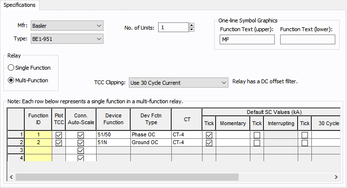
Figure 1: Specifications Tab
| Option | Description |
|---|---|
|
Mfr |
Provides a list of manufacturers available in the device library. If the desired manufacturer is not listed in the device library, you can add it to the library. |
|
Type |
Equipment types available from the selected manufacturer. If the desired type is not listed, you can add it to the library. A type is essentially a model name. |
|
No. of Units |
Number of relay units of the same type that are part of a relay system. |
|
One-line Symbol Graphics |
You can make the desired text appear inside the relay symbol by typing in Function Text (upper) and Function Text (lower). You can type up to 4 characters each. EasyPower assigns the text “R” in the upper field by default. |
|
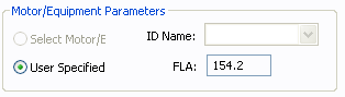
Motor/Equipment Parameters |
These are parameters of the equipment being protected by the relay. For example, a motor relay would require the full load current as a parameter.
|
|
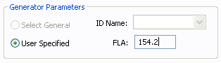
Full load amps (FLA) of the generator is entered here. This section appears in the dialog box only for those relays which have been entered in the library as generator protection relays. EasyPower calculates pickup amps from FLA and pickup setting.
|
|
|
Number of trip units or relay functions set differently. You can select either Single Function or Multi-Function. One device function can have a time-overcurrent function and an instantaneous over-current function. A relay with only one device function is a single function relay. A multi-function relay may have more than one device function. For example, a relay with time-overcurrent and instantaneous over-current trip functions for phase current, negative sequence current and ground current, is a multi-function relay. The description of different device functions is entered row by row. If you select Single Function, you will be able to enter only device function. If a relay has been entered in the library as a single function relay, then you cannot select it as a multi-function relay. |
|
|
TCC Clipping |
Select the type of fault current to use to clip the relay TCC. Select <None> to avoid clipping. |
|
Breaking |
For IEC, you can select the breaking values. The options are Global, 0.02, 0.05, 0.1, or 0.25. Global is derived from the Short Circuit Options on the Control tab. |
|
A unique ID name for each device function in the relay. The ID name can have up to 12 characters. Type the desired ID name. |
|
|
Plot TCC |
Check box to enable plotting TCC. Any device function with the check box not selected results in a plot without the TCC of that device function. |
|
Conn. Auto-Scale |
When this check box is selected, the program automatically scales the TCC curves based on the phase connection type. Traditionally, for 3PH curves in a TCC, scaling the curves based on the reference voltage is adequate. If a line-to-neutral connected 1PH device is to be plotted with an upstream 3PH device, then the LN connected 1PH curve needs to be shifted by a factor of the SQRT(3) in addition to the voltage-based scaling. Similarly, if a line-to-neutral connected 1PH device is to be plotted with an upstream 1PH-3W device, then the LN connected 1PH curve needs to be shifted by a factor of the 2 in addition to the voltage-based scaling.When the check box is not selected, scaling based on the phase connection type is not applied. The check box status for individually stored TCC plots can be different. The default for new TCC plots is obtained from the database for the device. |
|
Device Function |
Provides a list of device functions available for the relay. The Relay Device Functions table below displays ANSI/IEEE relay device functions modeled in the EasyPower library. The table includes suffixes added to clarify applications. |
|
Dev Fctn Type |
The device function type provides the description of the selected relay function. Arc flash calculations may or may not use the device function trip time based on the device function type. For example, while performing a 3-phase fault calculation, the device function type Ground OC is ignored and Phase OC and Maint Phase OC are included. The types Differential and Other are always excluded from arc flash calculations. |
|
CT |
Provides a list of current transformers connected to the relay in the one-line diagram. The CT ratio of the selected CT will be used in calculations to obtain TCC plots. In the one-line diagram, up to 6 CTs can be connected to a relay. In the case of multifunction relays, different CTs may be used for different device functions. |
|
To mark the short circuit values in the TCC plot select the box below Tick and enter the short circuit values in kilo amperes.
|
|
|
Breaker Trip |
Specify the breaker or switching device opened by the relay upon tripping. |
|
Eqp Type |
Select the switching device from HV Breaker, LV Breaker, Fuse and Switch. |
|
Eqp ID |
ID Name of the equipment on the one-line. |
|
Aux Time |
Additional relay time or time delay of auxiliary relays. For arc flash and auto-coordination calculations the Aux Time and HV breaker opening time are taken into account. |