Double-Click Tab
To set dynamic stability options, from the Dynamic Stability focus, click Stability. You can also access the options from within the Database Edit focus by selecting Tools > Options > Analysis Options > Dynamic Stability.
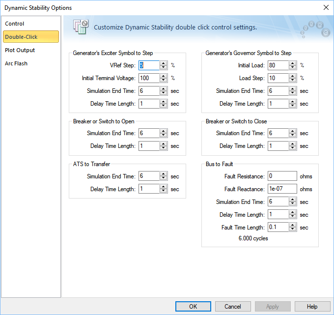
Figure 1: Dynamic Stability Options – Double-Click Tab
| Option | Description |
|---|---|
|
Generator’s Exciter Symbol to Step A step response test on the exciter of a generator lets you to see the effect of increasing the excitation by a specified amount. The AutoPlot tab plots the per-unit generator terminal voltage and the per-unit field voltage. This test treats the generator as isolated from the network. The step test is performed by double-clicking on the generator exciter symbol in the one-line. These options are available only if Dynamic Stability has been purchased. |
|
|
Vref Step |
This is the percent increase in the reference voltage. |
|
Initial Terminal Voltage |
The terminal voltage in percentage of rated voltage before the step is applied. |
|
Simulation End Time |
Simulation is run up to this time. |
|
Delay Time Length |
The step is applied after this delay after the simulation begins. For example, if you specify the delay time length as 1 second, then the step in Vref occurs 1 second after the simulation begins. |
|
Generator’s Governor Symbol to Step A step response test on the governor of a generator enables you to see the effect of increasing the load by a specified amount. The generator speed changes. The AutoPlot tab plots the per-unit generator prime mover power and the per-unit speed. The step test is performed by double-clicking on the generator governor symbol in the one-line. These options are available only if Dynamic Stability has been purchased. |
|
|
Initial Load |
Percent load on the generator at the beginning of the step response test. |
|
Load Step |
Percent increase in the generator load. |
|
Simulation End Time |
Simulation is run up to this time. |
|
Delay Time Length |
The step is applied after this delay after the simulation begins. For example, if you specify the delay time length as 1 second, then the step in the load occurs 1 second after the simulation begins. |
|
Breaker or Switch to Open You can double-click on a breaker or a switch to open or close it. |
|
|
Simulation End Time |
Simulation is run up to this time. |
|
Delay Time Length |
The breaker or switch is opened after the specified delay after the simulation begins. For example, if you specify the delay time length as 1 second, then the breaker or switch opens 1 second after the simulation begins. |
|
Breaker or Switch to Close |
You can double-click on a breaker or a switch to open or close it. |
|
Simulation End Time |
Simulation is run up to this time. |
|
Delay Time Length |
The breaker or switch is closed after the specified delay after the simulation begins. For example, if you specify the delay time length as 1 second, then the breaker or switch closes 1 second after the simulation begins. |
|
ATS to Transfer You can double-click on an ATS to transfer the connection to the alternate source. |
|
|
Simulation End Time |
Simulation is run up to this time. |
|
Delay Time Length |
The ATS connection is transferred to an alternate source after the specified delay after the simulation begins. For example, if you specify the delay time length as 1 second, then the ATS transfers the connection 1 second after the simulation begins. |
|
Bus to Fault You can double-click on a bus to simulate a bus fault (short circuit). |
|
|
Fault Resistance |
Resistance at the fault point in ohms. A bolted fault has the fault resistance of zero. |
|
Fault Reactance |
Reactance at the fault point in ohms. A bolted fault has the fault reactance of zero. |
|
Simulation End Time |
Simulation is run up to this time. |
|
Delay Time Length |
The fault is performed on the bus after the specified delay after the simulation begins. For example, if you specify the delay time length as 1 second, then the fault occurs 1 second after the simulation begins. |
|
Fault Time Length |
The duration for which the fault lasts. If the fault time length is specified as 0.1 seconds, the fault is removed automatically 0.1 seconds after the fault is applied. |