Phase Connector Symbols on the One-line
When any single-phase equipment is fed from another equipment upstream and its conductor configuration is different from the upstream equipment, a symbol appears in the one-line to indicate the connection property is different at the point of connection. Where connection properties are similar the connector symbol is not displayed. We refer to this symbol as a phase connector.
The phase connector symbol appears as two diagonal slash marks below the point where the single-phase tap is made.
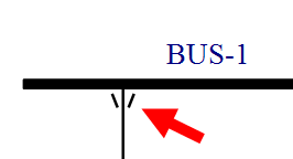
Figure 1: Phase Connector Symbol
You can turn the phase connector symbol visibility on or off globally in Tools > Options > One-line Symbols. See One-line Symbols Tab for more information.
The phase connector symbol is visible on one-lines, drawings, TCCs, print, and DXF outputs.
Tip: Hover the mouse pointer over the phase connector symbol to display the connection type in a tool tip.