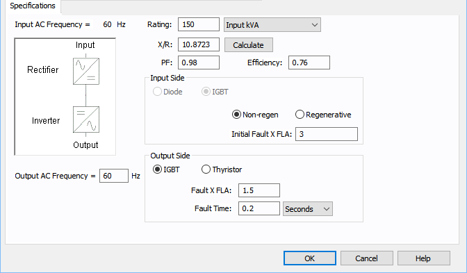
AFD - Specifications Tab
| Option | Description |
|---|---|
|
Input AC Frequency |
The fixed frequency on the input side. This is specified in the System tab of Options dialog box. |
|
Output AC Frequency |
The adjustable frequency on the output of the AFD. This affects the frequency of all equipment connected on the output of the AFD. |
|
Rating |
Rated Input kVA or the motor HP of the drive. |
|
X/R |
If the AFD is regenerative, this value is used to define the short circuit X/R ratio of the contribution delivered at the input of the AFD. The Calculate button uses an ANSI standard lookup table to fill in this value. |
|
PF |
The input power factor of the AFD for power flow simulations. |
|
Efficiency |
The efficiency of the AFD. This creates a real power increase from the output to the input of the AFD. |
|
Input Side |
|
|
Diode / IGBT |
This is currently IGBT only. |
|
Non-regen / Regenerative |
Select Non-regen to simulate a non-regenerative drive and Regenerative to simulate a regenerative drive (which includes a short circuit contribution on the input of the AFD). |
|
Initial / Momentary Fault x FLA |
The defined bolted fault level for the input of the AFD if it is regenerative. The label displayed is based on the IEC or ANSI option selected to Tools > Options. |
|
Output Side |
|
|
IGBT / Thyristor |
Select IGBT to model a source inverter on the output, or choose Thyristor to model a Thyristor output. This currently does not affect any calculations. |
|
Fault x FLA |
The fault current output of the AFD under a bolted fault condition. |
|
Fault Time |
The time that Fault x FLA is produced by the AFD under fault conditions |

