Switchgear Elevation
If you have defined the bus type as switchgear, you can view the elevation for the switchgear. In the Bus Data dialog box, on the Switchgear tab, you can specify whether the elevation layout is based on columns or rows. For columns, the breakers in one unit will be vertically stacked. For rows, you can have single breakers throughout the row (2X), or breakers on the left (1X-Left) or right (1X-Right).
For column-based elevation, specify the Column Number and Row Space for each row of data. This creates the elevation view.
Column Based
- Column Number: This is the number of the column in which the cubicle (for breakers) is located. The columns are arranged in increasing order starting from 1 and ending in the highest column number. See the pictures below of Equipment Elevation and the corresponding Switchgear tab.
- Row Space: Height of the space in terms of the column width.
Row based
Column Space: You can specify the size and side of the breaker spare in the panelboard. The breakers appear in order, with the first row showing at the top.
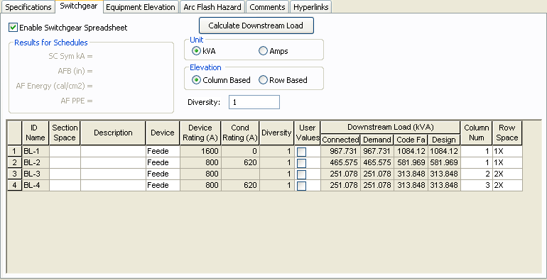
Figure 1: Column Number and Row Space on the Switchgear tab of the Bus Data Dialog Box
You can show the text for Equipment Name, Section Space, Description and Device Rating by setting the values in the Property pane.
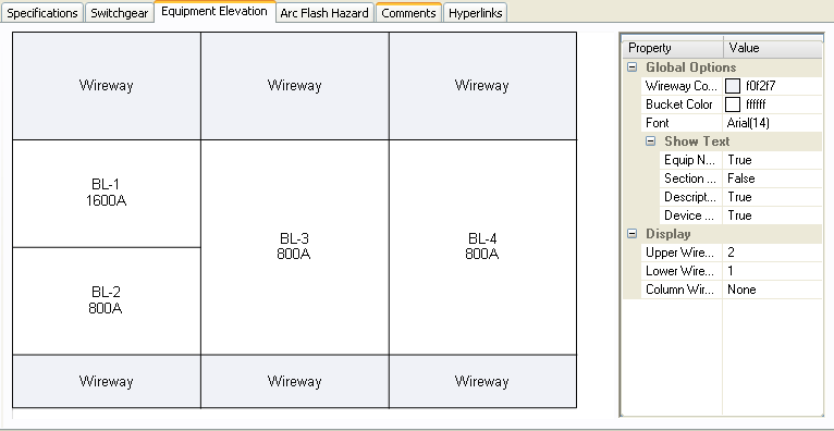
Figure 2: Switchgear Elevation
In the Property pane on the right of the elevation, you can:
- Specify the height for the top and bottom horizontal wireways and the vertical wireway.
- Change the column number and space size by selecting the cubicle first in the elevation and then changing the parameters.
Inserting rows in the Switchgear spreadsheet: You can right-click on the spreadsheet and click Insert Row or Append Row.
To print the elevation view, click  Print on the Bus Data dialog box toolbar.