Bus - Switchgear/Panelboard/Switchboard Tab
This tab allows you to calculate downstream loads on all the branches breakers connected to the bus. This tab can be labeled as Switchgear, or Panelboard, or Switchboard depending on the Bus Type selected in the Specifications tab.
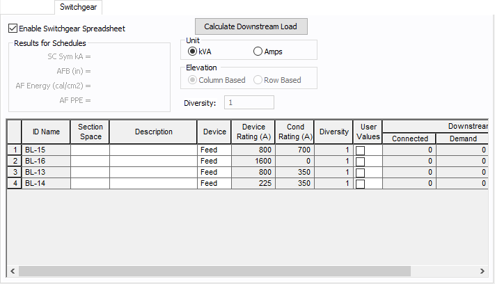
Figure 1: Switchgear Tab of Bus Data Dialog Box
| Option | Description |
|---|---|
|
Enable Switchgear Spreadsheet |
Selecting this check box enables you to modify information, enter load data and calculate downstream loads. Once you make the necessary data entry and calculations you can you can clear the check box to prevent changes. When the check box is not selected, the data can still be read, but not changed. |
|
Calculate Downstream Load |
Clicking this button calculates all downstream loads for each breaker, fuse, or branch connected to this bus. All branches are considered downstream unless there exists a source such as a UPS, generator or utility in the direction of the branch. The program traverses through all the paths and determines whether or not there is a power source in the path. All loads are summed and reported in the spreadsheet if there is no power source in the path. Single-Phase Load Calculations: Load calculations for 1PH equipment follow the conventional load calculation method similar to 3PH systems. The only difference is that the current values are specific to 1PH and the equipment voltage. At any distribution point (such as a bus, panel, or MCC.), the apparent power (VA or kVA) is summed up first for each energized (hot or live) current-carrying conductor. The respective load current is calculated from the voltage for the line of circuit. For each branch circuit tapped off at the distribution point, the program keeps track of the phase connection type. For example, phase connection for 1PH branches could be AN, BN, CN, AB, BC or CA. During load calculations, downstream load values are applied to the correct phases at the upstream distribution point. The results are displayed under the column Downstream Load in the Summary tab of the Panel Data dialog box and in the Switchgear, Panelboard, or Switchboard tab of the Bus Data dialog box. |
|
Results for Schedules |
For the bus types ATS, switchgear, switchboard, panelboard, panel and MCC, you can fault buses and store the short circuit current and arc flash results in the database. These results can be displayed in schedules for switchgear, switchboard, panelboard, panels and MCCs. The stored results can also be viewed in the database browser and report. See Storing Short Circuit and Arc Flash Results for more information. |
|
Unit |
You can display downstream loads in kVA or Amps. |
| Elevation | You can choose the elevation layout of the switchgear such that protective devices in stacked in columns or rows. For columns, the breakers in one unit are stacked vertically. For rows, you can have a single breaker, or breakers on the left or right. See Elevation View for more information. |
|
Diversity |
Enter the diversity factor for the bus. The factor is used in calculating connected, demand, code, and design kVA. The diversity factor is the ratio of the sum of the maximum demands of the individual loads to the maximum demand of the entire system, including all of those loads. Enter a value between 1 and 10. |
| Spreadsheet Column Headings | |
|
ID Name |
ID name of the equipment connected to the bus. If any branch has a protective device such as a switch, fuse or breaker connected to the bus, then the ID name of the protective device is shown. Otherwise the branch ID name is shown. |
|
Section Space |
Text that describes the space for the protective device or branch. |
|
Description |
Text that describes the branch connected to this bus. |
|
Device |
You can specify the protective device or branch as Feeder, Main, or Tie. This is for information only and does not affect calculations. |
|
Diversity |
The number shown is the diversity factor of the downstream bus with an equipment type of Switchgear, Switchboard, or Panelboard. If another equipment type is selected, the diversity factor is set to 1. Diversity factor is used in calculating the connected, demand, code and design kVA. The diversity factor is the ratio of the sum of the maximum demands of the individual loads to the maximum demand of the entire system, include all of those loads. Click Calculate Downstream Load to update the diversity factor. |
|
Device Rating (A) |
Continuous current rating of the protective devices in amps. |
|
Cond Rating (A) |
Amp rating of branch conductors. |
|
User Values |
Select the check box to manually enter a load. When checked, the entered values are used and the calculated downstream values from the one-line are ignored. |