Inverter - Power Flow Tab
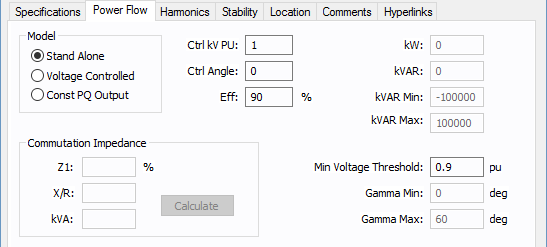
Figure 1: Power Flow tab of the Inverter Dialog Box
| Option | Description |
|---|---|
|
Model |
Describes the way the output of the inverter is controlled for IGBT type. The options are:
|
|
Ctrl kV PU |
The per unit magnitude of Inverter output voltage. This is maintained at the specified value for a Stand Alone model, and is maintained at the specified value while within var limits for a Voltage Controlled model. |
|
Ctrl Angle |
The angle in degrees of the controlled output voltage for Stand Alone model. |
|
Eff |
Efficiency of the inverter. This is the ratio between output and input power in percent. |
|
kW |
Specified controlled output active power in kW for Voltage Controlled and Const PQ Output models. |
|
kVAR |
Specified controlled output reactive power in kVAR for Const PQ Output models. |
|
kVAR Min |
Minimum kVAR capability of the inverter in voltage controlled mode. |
|
kVAR Max |
Maximum kVAR capability of the inverter in voltage controlled mode. |
|
Min Voltage Threshold |
For an IGBT inverter only, if the DC voltage on the input to the inverter drops below this value, then the inverter begins stepping its specified kW loading down until the input voltage rises above Min Voltage Threshold. Note: The power flow will not solve when loading on photovoltaics causes them to experience a severe terminal under-voltage. Therefore, this special control was added so that inverters fed by photovoltaics reduce load when voltage drops below VMP so that photovoltaics are required to supply less power, thus helping the DC voltage on the photovoltaics increase into a range where a power flow solution can be reached. |
|
Gamma Min |
Minimum inverter margin angle in degrees for thyristor type inverter. |
|
Gamma Max |
Maximum inverter margin angle in degrees for thyristor type inverter. |
|
Commutation Impedance |
Commutation impedance used to calculate the power flow using Kimbark’s equations with Thyristor type. The inverter must feed a dedicated transformer that matches these same values one-for-one.
|
More Information
- Inverter Data
- Database Dialog Box Toolbar
- Inverter - Connection Information
- Inverter - Specifications Tab
- Inverter - Harmonics Tab
- Inverter - Stability Tab
- Inverter - Reliability Tab
- Inverter - Location Tab
- Inverter - Comments Tab
- Inverter - Hyperlinks Tab
- Inverter - Collected Data Tab
- Inverter - Media Gallery Tab