Setting the Reference Bus for TCC Scaling
When you plot a TCC in the Coordination focus, you will get a plot similar to the one shown below. Note that the horizontal axis of the plot has a voltage reference that includes a reference bus.
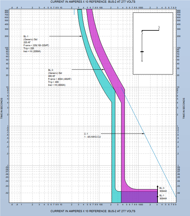
Figure 1: TCC for Single-Phase Equipment
If there were only 3PH equipment in the TCC it would be sufficient to scale all equipment curves based on voltage only. When single-phase equipment is included, the phase connection type requires additional factors to be considered while overlaying the curves on a common plot.
In this example all curves are scaled to the LN connected 277V BUS-2. Any fault current at this bus will also result in the same fault current at the upstream 3PH 480V bus. Therefore, to overlay the curves based on voltage and connection type, the BL-3 curve needs to be shifted to the left by a factor of 1/√3. This is done automatically.
In the one-line window of the left side of the TCC plot, you can right-click on the bus you want to use as the reference and select Set as Reference for TCC Scaling.
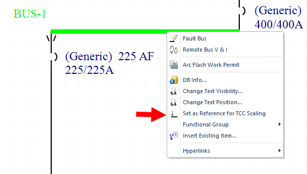
Figure 2: Set as Reference for TCC Scaling Option
This changes the reference bus and voltage and shifts the curves accordingly, as shown below.
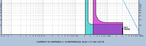
Figure 3: Horizontal Axis and TCC Scale