Plotting User Selected Values – Define Plot
When you perform a simulation by double-clicking on the one-line, data is plotted in the AutoPlot tab. Based on the type of simulation, EasyPower selects the values to display in the AutoPlot. For example, if you double-click on an open motor breaker or switch to start a motor, the plot is provided with motor per-unit values for voltage, current, speed and torque. To see values elsewhere in your system, you need to define plots. Nine plots are available with up to a maximum of 5 curves per plot.
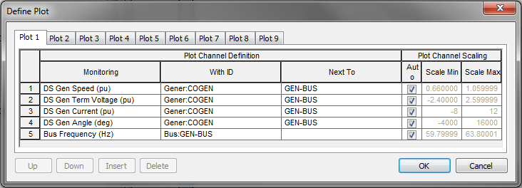
Figure 1: Define Plot dialog
To define a plot, on the Stability tab, click  Define Plots. In the Define Plot dialog box, select the values to plot by choosing the desired fields for Monitoring, With ID and Next To.
- Monitoring: Variable to be plotted. Example: voltage, current, power, torque, and so on.
- With ID: ID name of the equipment for which the variable is to be plotted.
- Next To: ID name of the bus to which the equipment is connected.
Note: Only activated items are available to plot.
You can also select values by first selecting on an open Monitoring cell, and then right-clicking the desired equipment on the one-line, and selecting the desired value type to be plotted with the Define Plots dialog box open. The entire row is automatically populated.
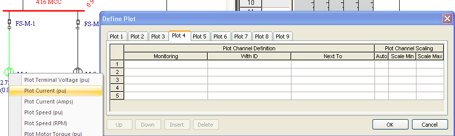
Figure 2: Define Plot Using One-line Selection
The following values are able to be plotted in a dynamic simulation, if the appropriate equipment is being modeled and is in existence and enabled.
|
Value |
Units |
Comment |
|---|---|---|
| Bus | ||
|
Voltage |
pu |
|
|
Voltage |
kV |
|
|
Fault I |
pu |
|
|
Fault I |
Amps |
|
|
Angle |
Degrees |
|
|
Frequency |
pu |
|
|
Frequency |
Hz |
|
|
AF Energy |
Cal/cm/cm |
If AF Fault Enabled |
|
Network Dev |
||
|
Current |
pu |
See Note 1 |
|
Current |
Amps |
See Note 1 |
|
kW |
kW |
See Note 1 |
|
kVar |
kVar |
See Note 1 |
|
DS Motor |
||
|
Term Voltage |
pu |
|
|
Current |
pu |
|
|
Current |
Amps |
|
|
Speed |
pu |
|
|
Speed |
RPM |
|
|
Torque |
pu |
|
|
Load Torque |
pu |
|
|
Watts |
pu |
|
|
Vars |
pu |
|
|
kW |
kW |
|
|
kVar |
kVar |
|
|
Angle |
deg |
Sync Motor Only |
|
Field Voltage |
pu |
Sync Motor Only |
|
Power Angle |
deg |
Sync Motor Only |
|
D-Axis Current |
pu |
Sync Motor Only |
|
Q-Axis Current |
pu |
Sync Motor Only |
|
Psi''d |
pu |
Sync Motor Only |
|
Psi''q |
pu |
Sync Motor Only |
|
DS Gen |
||
|
Current |
pu |
|
|
Current |
Amps |
|
|
Speed |
pu |
|
|
Speed |
RPM |
|
|
Torque |
pu |
|
|
P Mechanical |
pu |
|
|
Watts |
pu |
|
|
Vars |
pu |
|
|
kW |
kW |
|
|
kVar |
kVar |
|
|
Field Voltage |
pu |
|
|
Angle |
deg |
Machine Angle |
|
Term Voltage |
pu |
|
|
Power Angle |
deg |
|
|
D-Axis Current |
pu |
Id |
|
Q-Axis Current |
pu |
Iq |
|
Psi''d |
pu |
Flux ψ’’d |
|
Psi''q |
pu |
Flux ψ’’q |
|
VPSS |
pu |
PSS Output Voltage |
|
AVR Out |
pu |
|
Network Dev values are those that have no Dynamic Stability Model defined, and include:
- Capacitors
- Loads
- Shunts
- Filters
- Motors (Non DS Model)*
- Generators (Non DS Model)*
- Utilities
- UPS
- Breakers
- Switches
- Tie Breakers
- Tie Switches
- Cables
- Overhead Lines
- Two Winding Transformers
- Three Winding Transformers
- Busway
- Current Limiting Reactors
* For non-DS motors and generators, we mean that no model is defined in the Stability tab of the motor or generator data dialog, or their Enable check box is not selected.