Tutorial - Panel Schedules
This tutorial provides a brief description of EasyPower panel schedules.
Creating a Panel Schedule
- Open a new one-line by clicking File > New > New Oneline.
- Click
 Maximize on the one-line window, if needed, to fill the session window with the one-line.
 - In the Equipment Palette, select
 Panel Schedule. The pointer changes to a panel symbol. Click anywhere on the one-line to place the panel schedule.
Tip: If you are viewing the Start Page, you can click New to open a blank one-line.
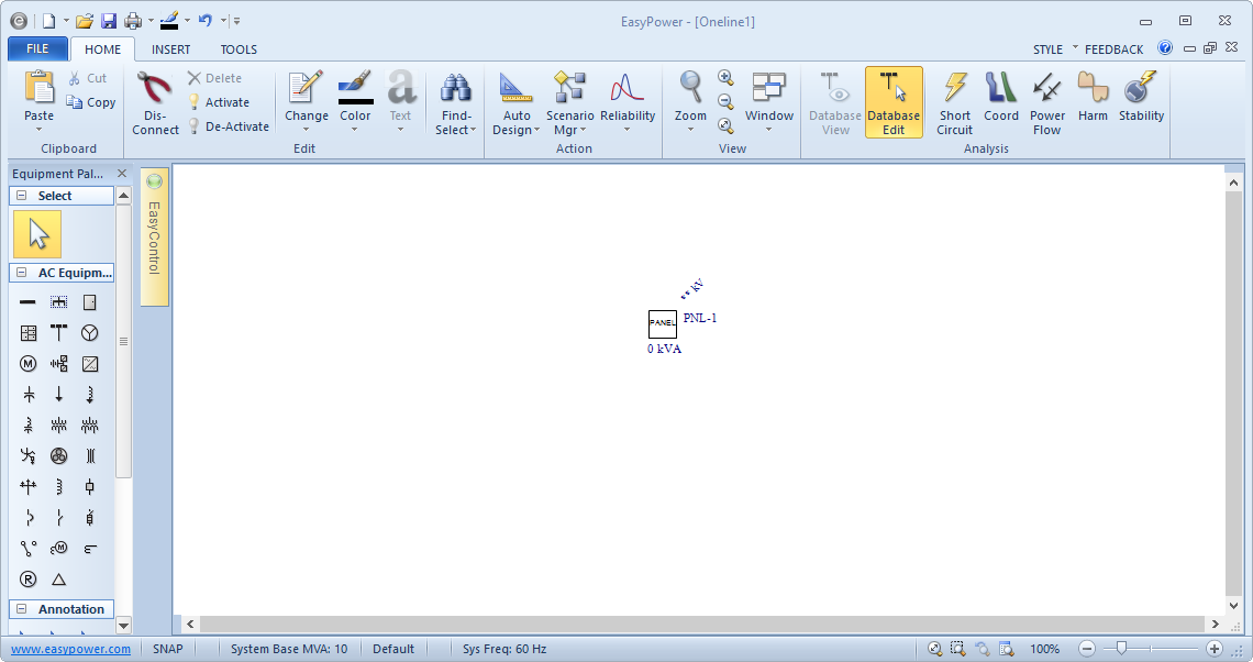
Figure 1: One-line View of a Panel Schedule
Depending on your settings, you may need to click Panel Schedule again or click the  Select arrow to return to the pointer.
Entering Panel Schedule Data
- Double-click on the panel you just added to the one-line.
- In the Connection Information area, note the red exclamation mark next to the Base kV box, indicating it is required. Type 0.48 into the box.
- Click the Description tab. In the Panel Schedule Spreadsheet Creation Wizard dialog box, select 6 as the number of rows you want to create. This equates to a 12-circuit panel. Click OK.
- On the Description tab, under View, ensure Detailed - Both Sides is selected.
- Enter data in the panel spreadsheet just like you would in other standard spreadsheets such as Excel. The data is validated as you enter it.
- In the first row on the left spreadsheet, type 3 under CB/Fuse Poles. (You may need to scroll right to find this column.) Then click on a different cell so the change in the CB/Fuse Poles cell is stored.
- In the first row on the right spreadsheet, type 2 under CB/Fuse Poles. Then click on a different cell so the change in the CB/Fuse Poles cell is stored.
- Fill in all the VA(A), VA(B), and VA(C) cells for both sides of the panel as shown in Panel Spreadsheet Loads. Notice that the single-phase 2500VA load gets input in only one of the VA cells (VA(C)). The two-phase load gets its 7000VA loads entered in two of the phases (VA(A) and VA(B)). The three-phase load gets its loads entered in all three phases.
- Select the Summary tab of the Panel Data dialog box. General information calculated from the panel spreadsheet data is displayed here.
- Select the Power Flow tab.
- Click OK to close the Panel Data dialog box.
In the Panel Data dialog box, note that there are several tabs. The Specifications tab contains entry fields for panel information. Most of these are not required for analysis calculations. For this tutorial, assume that units are set to US, not Metric.
Note: You can resize the Panel Data dialog box window by dragging its edges. You can also maximize the dialog box on your screen by clicking the  Maximize button.
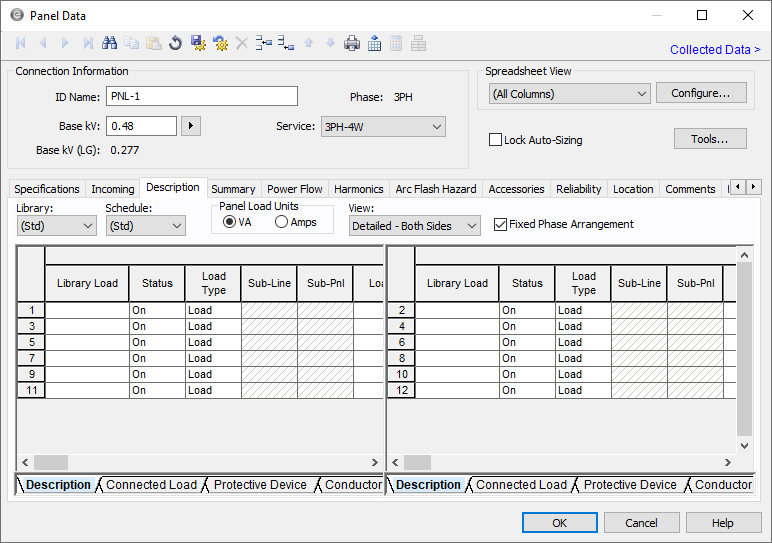
Figure 2: Panel Schedule Spreadsheet
The panel spreadsheet toolbar includes additional options when you view the Description tab (see below). You must click somewhere in the spreadsheet to make the toolbar buttons available.
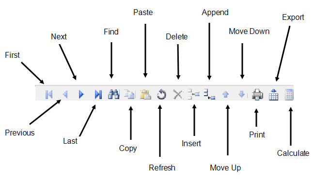
Figure 3: The Panel Spreadsheet Toolbar
The spreadsheet has its own scroll bars to use for moving around. You can also use the tabs at the bottom of the spreadsheet (shown below) to move to different sections of the spreadsheet.

Figure 4: Panel Spreadsheet Sections
Typical panelboard circuits are lined up in two columns: one on the left side of the panelboard and one on the right. The EasyPower panel spreadsheet is laid out in the same manner (see Panel Schedule Spreadsheet). Each spreadsheet row represents two circuit poles—one on the left and one on the right.
To model a two-phase or three-phase load in panels, simply specify the number of poles in the CB/Fuse Poles column.
With the exception of the load columns, the next two rows on the left spreadsheet are no longer available as shown in Panel Spreadsheet Loads. Each row on the left side represents a pole or phase. When the Fixed Phase Arrangement check box is selected, the load data for the three rows (phases) are specified in a diagonal pattern for each phase.
Only one extra row gets disabled as shown on the right in Panel Spreadsheet Loads. The load data for the row can be entered, but other fields in the row are not available.
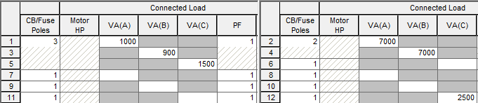
Figure 5: Panel Spreadsheet Loads
Cells that have inadequate data for analysis purposes are highlighted in red. There are no red cells displayed here since by default the panel spreadsheets already contain the minimum data required to run analysis calculations.
Cells that can be calculated (using the button) are indicated by bold column headers. For example, the Int kA cell in the Protective Device section can be calculated as shown in Calculable Cells With Bold Headers. To calculate this field, the other protective device information for that row must be entered.
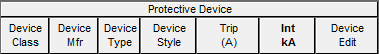
Figure 6: Calculable Cells With Bold Headers
You can enter protective device and conductor information, but the data is not required for analysis calculations.
Under Description, you will notice a Library Load column. This is for advanced panel spreadsheet users who want to enter typical panel circuits in their user-editable device library. After predefining a library load in Stdlib.mdb (the device library), selecting that library load in the panel spreadsheet automatically fills in the rest of the cells for that entire circuit.
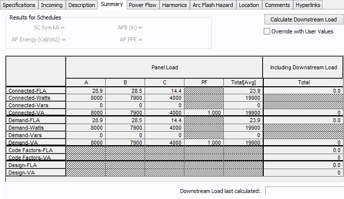
Figure 7: The Panel Summary
Note that there is also a Total column in the Including Downstream Load section. When you click Calculate Downstream Load, EasyPower automatically traverses your system to add up downstream load.
There are no sources in this system yet, so the downstream load is not calculated in this example. In the traversing algorithm, EasyPower uses sources to determine upstream branch direction.
The Connected kVA is the vector sum of all the connected VA values converted to kVA units. You have the option of using Demand, Code Factors, or Design kVA values as well.
Panels in Analysis
If you are an advanced EasyPower user, you can add a cable, a bus and a utility as shown in Performing Short Circuit Calculations on a Panel and have EasyPower perform short circuit, power flow and harmonics calculations on this small system.
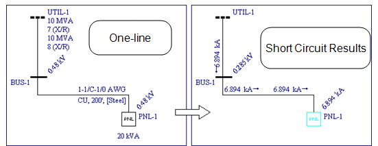
Figure 8: Performing Short Circuit Calculations on a Panel
Conclusion
This has been a brief overview of EasyPower’s panel schedule equipment. The EasyPower Help topics cover this and other features in greater
depth. To open Help, click  Help in the upper-right corner of the EasyPower window or press F1.