Tutorial – Single-Phase Modeling
This tutorial demonstrates how to build a one-line with single-phase (1PH) equipment. The key steps include inserting single-phase equipment, making connections of various wire configurations, and setting the service type for single-phase equipment. After the one-line and the equipment data are completed, you can perform analysis such as short circuit, arc flash and coordination on single-phase equipment.
Build the One-line
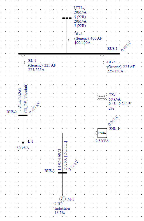
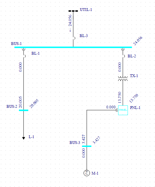
Follow the steps in this tutorial to create the one-line shown below.
Add a Bus and Utility to a New One-Line
-
Click File > New > New One-line to start a new one-line.
-
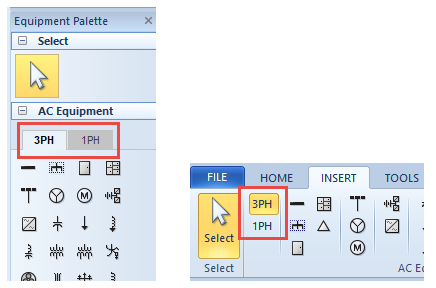
From the Equipment Palette (or the Insert tab) ensure the 3PH palette is selected, and then drag a bus to the one-line. (We will refer to the Equipment Palette for the remainder of this tutorial, but the steps are essentially the same for the Insert tab.) Double-click on the bus symbol to set the bus base kV to .480, and then click OK.
-
From the 3PH equipment palette, drag a utility and connect it to the bus on the one-line. Double-click on the utility symbol to enter the utility data as follows:
-
Utility kV: 0.48
-
Fault Duty Unit: MVA
-
3 Phase Short Circuit MVA: 20
-
X/R: 5
-
SLG Short Circuit MVA: 20
-
X0/R0: 5
-
Click OK to close the dialog box.
-
Stretch the length of the bus in the one-line. To do this, move the cursor to either end of the bus symbol and then click and drag the mouse pointer to stretch the bus length.
Tip: It is a good practice to save the file as you build the one-line.
Add a Single-Phase Cable, Load, and Breaker
To add single phase equipment:
-
First, select the 1PH tab in the Equipment Palette (or the button on the Insert tab).
-
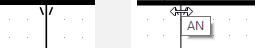
Drag a cable from the equipment palette. The text “1PH” appears next to the cursor to indicate a single-phase equipment item is being inserted (3-phase equipment does not show any text with the cursor).
-
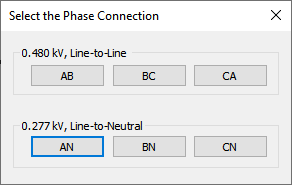
Connect the single-phase cable to the bus. The Select the Phase Connection dialog box is displayed.
-
The possible single-phase line-to-line connections from a 3-phase system are AB, BC, and CA.
-
The possible single-phase connections line-to-neutral connections from a 3-phase system are AN, BN, and CN.
-
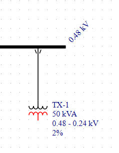
Next, insert a single-phase load to connect at the bottom end of the cable. Upon connection, a bus is automatically inserted between the cable and the new load. The new bus is automatically assigned the base kV of 0.277kV to reflect the line-to-neutral connection tapped off of a 3-phase 0.48kV bus.
-
Double-click the phase connector symbol to open the Select the Phase Connection dialog box. This enables you to change the phase connections for the circuit. For now, leave the connection as AN, but note that choosing a line-to-line connection such as AB, BC, or CA would make the base kV of the downstream bus invalid.
-
Double-click on the cable to open cable dialog box and enter the following data on the Specifications tab:
-
Unit: US
-
No/Ph: 1
-
Type: 1/C
-
Insulation: THWN
-
Size: 4/0
-
Conductor Material: Copper
-
Length: 75 feet
Ensure the impedances are auto-calculated and then click OK.
Note: If you are using the metric system, you can choose equivalent data.
-
-
Double-click on the load symbol and enter the following data on the Specifications tab:
-
Load Unit: kVA @ PF
-
Constant kVA: 50
-
PF: 0.8
Click OK to close the dialog box.
-
-
Insert a single-phase LV breaker in line with the cable and just below the phase connector symbol. Open the LV Breaker Data dialog to enter the following data on the Specifications tab:
-
Class : MCCB
-
Breaker Mfr: (Generic)
-
Breaker Type: Std
-
Breaker Style: 225AF
On the Short Circuit tab, click Calculate to import the short circuit rating.
On the Phase Trip tab, enter:
-
Frame: 225(150-225AT)
-
Trip Amps: 225
Instantaneous: HI (2250A)
Click OK to close the dialog box.
-
Click AN.
A phase connector symbol appears at the point of connection—this indicates that the phase or wire configuration is different from the upstream bus. You can hover over the phase connector symbol to display the connection information.
The phase connector symbol can be turned off in System Options. For now, leave it as-is.
Add a Single-Phase Transformer and Panel
-
Drag a single-phase two-winding transformer from the equipment palette and connect it to the 3-phase 0.48kV bus.
-
In the Select the Phase Connection dialog box, click BC. Note that the transformer automatically gets the voltage rating of 0.48kV on the primary side since this connection is line-to-line at the 3-phase bus.
-
Double-click on the transformer symbol and enter the following data:
-
Standard: ANSI
-
Type: Dry
-
Class: AA
-
Temp: 150
-
Form: Core
-
To Rated kV: 0.24
-
To Tap kV: 0.24
-
kVA Rating: 50
Select the check box for Center tap connection. This specifies the transformer as having a neutral grounded center-tap on the secondary winding (the "To" side), making the service type 1PH-3W. The system voltage for this is referred to as 120/240V.
Note: If you do not check this box the transformer secondary is treated as a 1PH-2W line-to-neutral service.
On the Impedance tab, for Z%, enter 2 and then click Calculate to get the X/R ratio.
Click OK to close the dialog box.
-
-
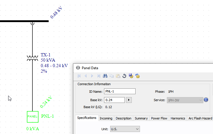
Drag a single-phase panel from the equipment palette and connect it to the secondary side of the transformer.
-
Double-click on the panel to view the connection data (see figure below). The base kV of 0.24 is inherited from the transformer. This is the line-to-line voltage. The line-to-neutral voltage is 0.12kV. The service field shows 1PH-3W.
Note: The blue information icon indicates that to change the Service you need to disconnect the panel first.
-
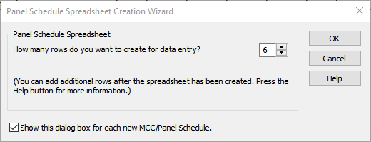
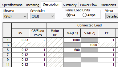
Click the Description tab in the panel dialog box. When prompted for the number of rows, type 6 and then click OK. This creates 6 rows on either side of the spreadsheet to fill out the branch circuit data.
-
In the spreadsheet, change the View to Detailed - Both Sides, and then scroll to the right to enter the load data as shown in the figure below. The first circuit is a two-pole circuit (rows 1 and 3) for which the load voltage is 0.230kV and the load is 2000 VA. The VA load is split equally between the load VA columns VA(L1) and VA(L2). Some may refer to the columns as A and B. In row 5, enter 0.12kV, 1 Pole and 500VA under column VA(L1).
-
Insert a single-phase LV breaker on the primary side of the transformer, and then enter the following data:
-
Class: MCCB
-
Breaker Mfr: (Generic)
-
Breaker Type: Std
-
Breaker Style: 225AF
On the Short Circuit tab, click Calculate to import the short circuit rating.
On the Phase Trip tab, enter the following data:
-
Frame: 225(150-225AT)
-
Trip Amps: 150
-
Instantaneous: HI (1500A)
Click OK button to close the dialog box.
-
Click OK to close the dialog box.
Add a Single-Phase Sub-Panel and Motor
Next, we will add a 120V circuit extending from the panel.
-
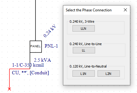
Insert a single-phase cable, starting from panel PNL-1 and drag left as shown in the figure below.
-
In the Select the Phase Connection dialog box, click L2N. The dialog box enables you to specify the desired connection type. From a 1PH-3W system you can connect:
-
1PH-3W (also referred to as LLN) equipment.
-
1PH-2W line-to-line (LL) connected equipment.
-
1PH-2W line-to-neutral (LN) connected equipment using L1 or L2 hot (line) conductors and neutral.
-
-
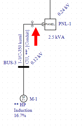
Insert a single-phase motor to connect at the bottom end of the cable. This automatically inserts a bus with the base kV of 0.12.
Drag the horizontal segment of the cable upwards to match the figure below. This helps to make the one-line neater and the phase connector easier to see.
-
Open the Cable Data dialog box and set the following parameters:
-
Unit: US
-
No/Ph: 1
-
Type: 1/C
-
Insulation: THWN
-
Size: 4
-
Conductor Material: Copper
-
Length: 50 feet
Ensure the impedances are auto-calculated and then click OK to close the dialog box.
-
-
Open the Motor Data dialog box and set the following parameters:
-
kV: 0.115
-
HP: 2
On the Short Circuit tab of the motor dialog box, click Calculate to obtain the X/R ratio.
Click OK to close the dialog box.
-
-
Open the dialog box for panel PNL-1.
On the Description tab, in Row 7 and the column Load Type, select Sub-Panel.
In the Sub-Line column, select Cab: C-2 to select the cable feeding the downstream motor.
Scroll to the right find the Device Edit column in the Protective Device section. In the same row click the Data button to display the LV breaker data. Enter the following data:
-
Breaker Mfr: (Generic)
-
Breaker Type: Std
-
Breaker Style: 50AF
On the Short Circuit tab, click Calculate to import the short circuit rating.
On the Phase Trip tab, enter the following data:
-
Frame: 50A
-
Trip Amps: 30
Click OK to close the LV breaker dialog box, and then click OK to close the panel dialog box.
-
-
To add a service entrance circuit breaker, first select the 3PH equipment palette, and then insert a 3-phase LV breaker in line with the utility.
Open the LV Breaker Data dialog and enter the following data:
-
Class: MCCB
-
Breaker Mfr: (Generic)
-
Breaker Type: Std
-
Breaker Style: 400 AF
On the Short Circuit tab, click Calculate to import the short circuit rating.
On the Phase Trip tab, enter the following data:
-
Frame: 400(400AT)
-
Trip Amps: 400
-
Instantaneous: 4000
Choose OK to close the dialog box.
-
The creation of the one-line is now complete. Save the file.
Short Circuit Analysis
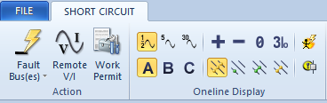
On the Home tab, click Short Circuit.
Note: If your data is not complete you will not be able to enter short circuit analysis. If there are any error messages for incomplete data, complete the data entry for the affected equipment.
Click Fault Buses to fault all buses to display the short circuit currents.
The fault type for the 3-phase bus can be selected from the Short Circuit tab.
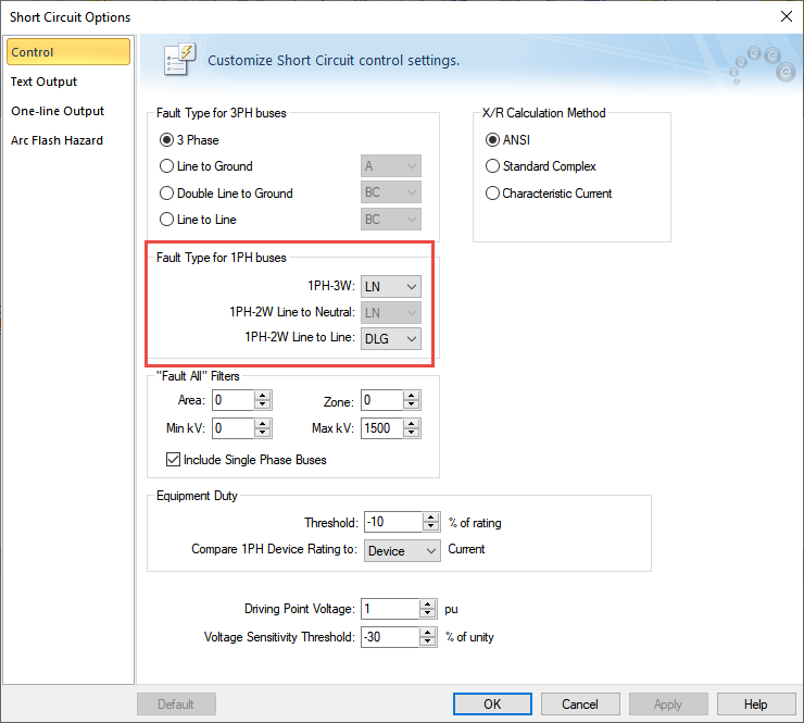
For a 1PH-3W panel that is fed by a center-tapped single-phase transformer you can get different results for line-to-ground or line-to-line fault. You can choose the single-phase fault type in the Control tab of the Short Circuit Options dialog box, as shown below. Line-to-ground fault current will be higher than the line-to-line fault current when the fault point is close to a transformer.
Coordination
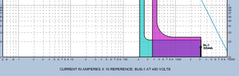
Open the Coordination focus. Select LV breaker BL-3 at the utility and all items in the circuit supplying the 50kVA load, and then click Plot TCC. You will get a plot similar to the one shown below.
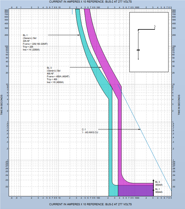
Note that the horizontal axis of the plot has a voltage reference that includes a reference bus. If there were only 3-phase equipment in the TCC it would be sufficient to scale all equipment curves based on voltage only. When single-phase equipment is included, consideration of phase connection is required in addition to voltage while overlaying the curves on a common plot.
In this example all curves are scaled to the LN connected 277V BUS-2. Any fault current at this bus will also result in the same fault current at the upstream 3-phase 480V bus. Therefore, to overlay the curves based on voltage and connection, the BL-3 curve needs to not be shifted despite the voltage difference of 1/√3. This is done automatically.
In the one-line window of the left side of the TCC plot, right-click on BUS-1 and select Set as Reference for TCC Scaling.
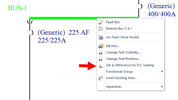
This changes the reference bus and voltage and shifts the curves accordingly, as shown below.
Close the TCC plot when you are done. You don't need to save the changes.
Arc Flash Analysis
Click once in a blank area of the one-line to remove the item selection before continuing.
-
Open the Short Circuit focus.
-
Click SC Options and on the Arc Flash Hazard tab, set Max Times to 2 seconds for both <0.25 kV and 0.25 to 1kV fields.
-
Click OK to close the dialog box.
-
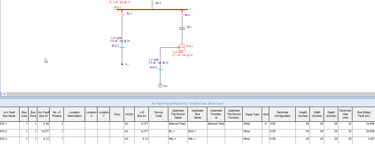
Click Arc Flash, click Fault Buses, and then click Arrange for Arc Flash. The arc flash results should look like those shown below.