Three Winding Transformer - LTC (Load Tap Changer) Tab

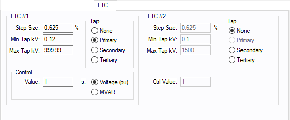
Figure 1: LTC tab of Three-Winding Transformer Data Dialog Box
| Option | Description |
|---|---|
|
Step Size |
The default is 0.625 but you can type in your own percentage step size both here and in the power flow three-winding transformer temporary dialog box. |
|
Min Tap kV |
Minimum tap kV is used to determine the bottom limit to which the tap can be adjusted during a power flow analysis. This value should be the lowest tap on the transformer to get meaningful results. The default of 0.12 kV is not realistic and should be changed to the actual values if the LTC is used. |
|
Max Tap kV |
Maximum tap kV, which is used to determine the upper limit that the tap can be adjusted to during a power flow analysis. This value should be the highest tap on the transformer to get meaningful results. The default of 1500 kV is not realistic and should be changed to the actual values if the LTC is used. |
|
Load tap changers (LTC) can be placed on one or two windings of a three-winding transformer. Any combination of primary, secondary or tertiary is allowed, provided that they do not specify the same winding. Also, if only one LTC is used, it must be LTC #1. If the transformer does not have an LTC, select None for standard fixed taps. Fixed off-nominal taps can be entered in the main dialog's Tap kV field. |
|
|
Control Value (Ctrl Value) |
Control value, which is determined by the Control Type field.
|
|
Control Type |
Determines how the LTC model is used.
|
More Information
- Three Winding Transformer Data
- Database Dialog Box Toolbar
- Three Winding Transformer - Connection Information
- Three Winding Transformer - Specifications Tab
- Three Winding Transformer - Impedance Tab
- Three Winding Transformer - TCC Tab
- Three Winding Transformer - Harmonics Tab
- Three Winding Transformer - Reliability Tab
- Three Winding Transformer - Location Tab
- Three Winding Transformer - Comments Tab
- Three Winding Transformer - Hyperlinks Tab
- Three Winding Transformer - Collected Data Tab
- Three Winding Transformer - Media Gallery Tab
