Excitation System Models
Simple Excitation System
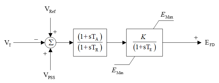
Figure 1: Simple Exciter Model Block Diagram
|
Parameter |
Units |
Description |
|---|---|---|
|
TA |
Seconds |
AVR Lead Time Constant |
|
TB |
Seconds |
AVR Lag Time Constant |
|
TE |
Seconds |
Exciter Time Constant |
|
K |
pu |
Exciter Gain |
|
EMin |
pu |
Exciter Min Limit |
|
EMax |
pu |
Exciter Max Limit |
IEEE Type 1
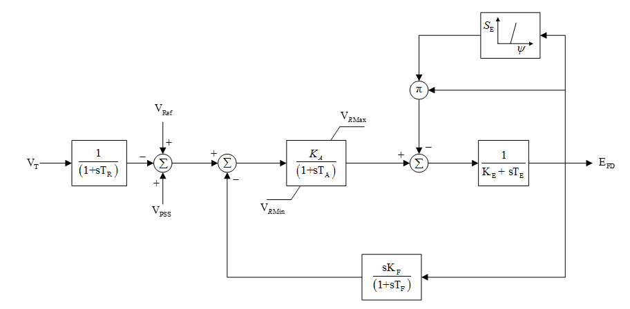
Figure 2: IEEE Type 1 Model Block Diagram
|
Parameter |
Units |
Description |
|---|---|---|
|
TR |
Seconds |
Transducer time constant |
|
TA |
Seconds |
AVR time constant |
|
TE |
Seconds |
Exciter time constant |
|
TF |
Seconds |
Field voltage feedback time constant |
|
KA |
pu |
AVR gain |
|
KE |
pu |
Exciter KE |
|
KF |
pu |
Field voltage feedback gain |
|
VR Max |
pu |
AVR limit max |
|
VR Min |
pu |
AVR limit min |
|
E1 |
pu |
Saturation voltage point 1 |
|
E2 |
pu |
Saturation voltage point 2 |
|
S( E1 ) |
pu |
Saturation at E1 |
|
S( E2 ) |
pu |
Saturation at E2 |
IEEE Type 2
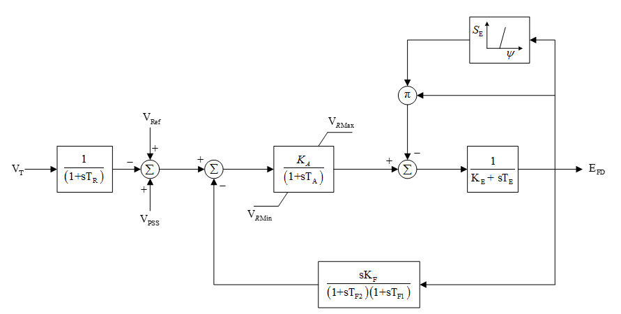
Figure 3: IEEE Type 2 Model Block Diagram
|
Parameter |
Units |
Description |
|---|---|---|
|
TR |
Seconds |
Transducer time constant |
|
TA |
Seconds |
AVR time constant |
|
TE |
Seconds |
Exciter time constant |
|
TF1 |
Seconds |
Field voltage feedback time constant 1 |
|
TF2 |
Seconds |
Field voltage feedback time constant 2 |
|
KA |
pu |
AVR gain |
|
KE |
pu |
Exciter KE |
|
KF |
pu |
Field voltage feedback gain |
|
VR Max |
pu |
AVR limit max |
|
VR Min |
pu |
AVR limit min |
|
E1 |
pu |
Saturation voltage point 1 |
|
E2 |
pu |
Saturation voltage point 2 |
|
S( E1 ) |
pu |
Saturation at E1 |
|
S( E2 ) |
pu |
Saturation at E2 |
Brushless Type AC1A
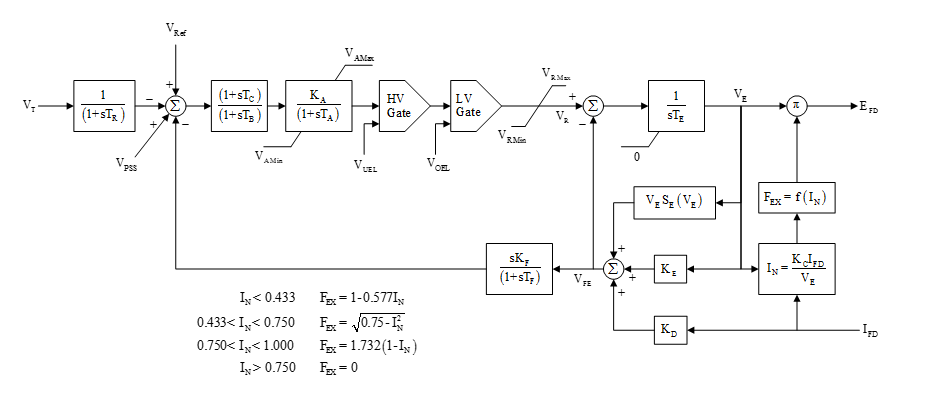
Figure 4: IEEE Type AC1A Model Block Diagram
|
Parameter |
Units |
Description |
|---|---|---|
|
TR |
Seconds |
Sensor time constant |
|
TA |
Seconds |
Main AVR time constant |
|
TB |
Seconds |
Second block AVR lag time constant |
|
TC |
Seconds |
Second block AVR lead time constant |
|
TE |
Seconds |
Exciter time constant |
|
TF |
Seconds |
Feedback lag time constant |
|
KA |
pu |
First block main AVR gain |
|
KC |
pu |
Exciter KC – Field current feedback |
|
KD |
pu |
Exciter KD – Field current feedback |
|
KE |
pu |
Exciter KE |
|
KF |
pu |
Feedback gain |
|
VAMax |
pu |
AVR control max |
|
VAMin |
pu |
AVR control min |
|
VRMax |
pu |
Regulator max - Amplifier |
|
VRMin |
pu |
Regulator min - Amplifier |
|
E1 |
pu |
Saturation voltage point 1 |
|
E2 |
pu |
Saturation voltage point 2 |
|
S(E1) |
pu |
Saturation at E1 |
|
S(E2) |
pu |
Saturation at E2 |
|
VUEL |
pu |
Fixed Under Excitation Limit |
|
VOEL |
pu |
Fixed Over Excitation Limit |
Brushless Type AC6A
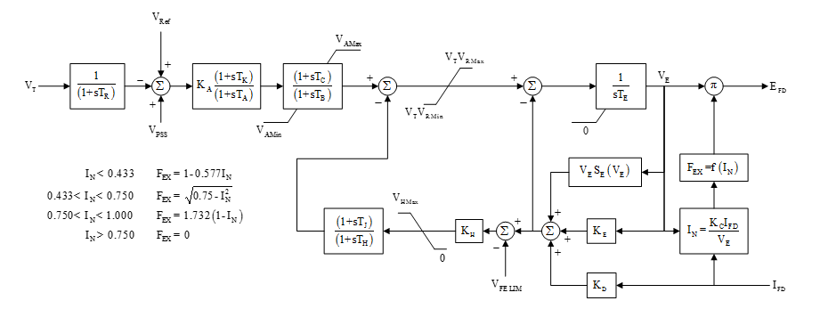
Figure 5: IEEE Type AC6A Model Block Diagram
|
Parameter |
Units |
Description |
|---|---|---|
|
TR |
Seconds |
Sensor time constant |
|
TK |
Seconds |
First block lead time constant |
|
TA |
Seconds |
First block lag time constant |
|
TB |
Seconds |
Second block lag time constant |
|
TC |
Seconds |
Second block lead time constant |
|
TE |
Seconds |
Exciter time constant |
|
TJ |
Seconds |
Feedback lead time constant |
|
TH |
Seconds |
Feedback lag time constant |
|
KA |
pu |
First block gain |
|
KC |
pu |
Exciter KC – Field current feedback |
|
KD |
pu |
Exciter KD – Field current feedback |
|
KE |
pu |
Exciter KE |
|
KH |
pu |
Feedback gain |
|
VFELim |
pu |
VFE limit value |
|
VHMax |
pu |
Feedback max |
|
VAMax |
pu |
AVR control max |
|
VAMin |
pu |
AVR control min |
|
VRMax |
pu |
Regulator max - Amplifier |
|
VRMin |
pu |
Regulator min - Amplifier |
|
E1 |
pu |
Saturation voltage point 1 |
|
E2 |
pu |
Saturation voltage point 2 |
|
S(E1) |
pu |
Saturation at E1 |
|
S(E2) |
pu |
Saturation at E2 |
Brushless Type AC8B
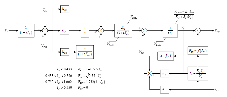
Figure 6: IEEE Type AC8B Model Block Diagram
|
Parameter |
Units |
Description |
|---|---|---|
|
TR |
Seconds |
Transducer time constant |
|
TA |
Seconds |
Main AVR time constant |
|
TE |
Seconds |
Exciter time constant |
|
TDR |
Seconds |
Differential time constant for PID control |
|
KPR |
pu |
Proportional gain for PID control |
|
KIR |
pu |
Integral gain for PID control |
|
KDR |
pu |
Differential gain for PID control |
|
KA |
pu |
Main AVR time constant |
|
KC |
pu |
Exciter KC – Field current feedback |
|
KD |
pu |
Exciter KD – Field current feedback |
|
KE |
pu |
Exciter KE |
|
VR Max |
pu |
Regulator max - Amplifier |
|
VR Min |
pu |
Regulator min - Amplifier |
|
VE Max |
pu |
Exciter max |
|
VE Min |
pu |
Exciter min |
|
E1 |
pu |
Saturation voltage point 1 |
|
E2 |
pu |
Saturation voltage point 2 |
|
S(E1) |
pu |
Saturation at E1 |
|
S(E2) |
pu |
Saturation at E2 |
