Global TCC Changes vs. TCC Dependent Changes
This section describes the difference between global TCC changes and TCC dependent changes. In general, global TCC changes affect all open TCCs, while TCC dependent changes affect only the active TCC.
Global Changes
Equipment Trip Settings: This includes all equipment setting information (manufacturer, pickup, instantaneous, and so on).
TCC Dependent Changes
Short Circuit Settings: This includes tick mark check boxes, clipping specifications, and all user-entered kA values.
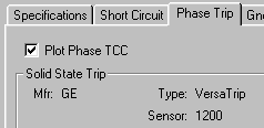
TCC Plot Checkboxes: This includes Phase Trip, Ground Trip, Fuse, Mtr O/L, and so on. See the picture below for an example.

Figure 1: Example Plot Check Box
TCC Appearances: This includes TCC curve colors, styles, and line types. This also includes TCC plot area formatting, title block formatting, and so on.
TCC Options: These primarily relate to which short circuit currents are used in a TCC. This includes the option to select between User-Specified values and Calculated from Short Circuit values.
Global and TCC Dependent Issues
In general, data entered from the main one-line becomes the user-defined default for new TCC plots.
Changes made to equipment trip settings affect all open TCCs. This includes modifications made from both a TCC and the main one-line. This is because device settings are universal rather than plot dependent.
- If user-specified values are used in a TCC instead of calculated short circuit values, the user-specified values entered from the main one-line become the assumed currents for all new TCCs.
- If calculated short circuit currents are used in a TCC, the user-specified values are ignored. Instead, the settings in TCC Options determine which short circuit calculations are used.
Note: When using the user-specification option to enter TCC short circuit values, we recommend specifying from the main one-line which currents new TCCs use by default. This saves time by ensuring all new TCCs contain the currents most often preferred (typically 3-phase momentary currents). If a particular TCC requires different currents (such as grounding currents), this can be modified for that individual TCC.
Changes made to plot check boxes affect only the active TCC. This enables different curves to be used for phase and ground coordination.
Note: Much like the short circuit currents, we recommend specifying from the main one-line which curves to plot by default. This saves time by ensuring that all new TCCs plot the curves most often used. If a particular TCC requires different curves plotted (such as ground trip curves), this can be modified for that individual TCC.
