TCC Options
TCC options can be used in the  TCC Options from the TCC tab.
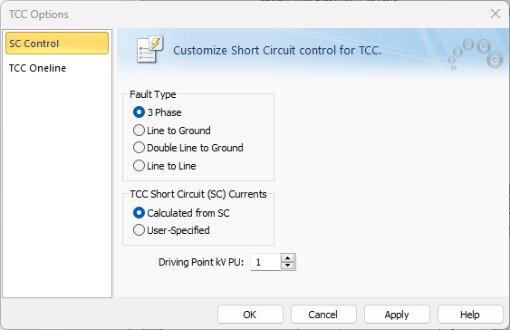
Figure 1: SC Control Tab of TCC Options Dialog Box
Note: If the system options are set to IEC-60909, the X/R Calculation Method area is not displayed.
Short Circuit Control Tab
|
Option |
Description |
|---|---|
|
Four different types of faults are available during a short circuit analysis. The default is 3 Phase, which is generally used to determine the highest available currents for equipment duty comparisons, and relaying. You can also select 3 Phase fault by clicking The other types, Line to Ground, Double Line to Ground, and Line to Line are generally used for specialized relaying applications or system trouble shooting. The green dots in the buttons indicate the ground fault type. |
|
|
TCC Short Circuit Currents |
The short circuit currents used in the TCC can be calculated from short circuit or user-specified.
|
|
System fault point voltage in per-unit. This value defaults to 1.0 per-unit. |

TCC One-line Tab
The contents of the One-line Output tab of the TCC Options dialog box are the same as those described for Short Circuit Options dialog box. See One-line Output Tab or One-Line Output Tab (IEC) for more information.