HV Breaker Data

This dialog box includes the following areas and tabs:

See Common Tabs for information on the Location, Comments, Hyperlinks, Media Gallery, or Collected Data tabs.

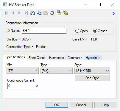
Figure 1: HV (High Voltage) Breaker Data Dialog Box

Connection Information

Option Description
ID Name

Uniquely identifies the equipment item. The program automatically assigns a name, but you can change it, if needed. The name can be up to 16 characters long.

For high voltage breakers, the program automatically assigns the names BH-1, BH-2, BH-3, and so on.

Open/Closed Normal state of the high voltage breaker. If Open is selected, the one-line will displays “OPEN” next to the high voltage breaker symbol. If Closed is selected, the one-line symbol does not display any text.
On Bus The bus to which the high voltage breaker connects, which must already exist on the one-line. For your reference, the On Bus base kV is displayed next to the bus name.
Connection Type Whether the high voltage breaker is connected as a “Feeder,” (such as to a cable, busway, transformer) or as a “Tie” (between two buses).

Specifications Tab

Option Description
Mfr

Provides a list of manufacturers available in the device library. If the desired manufacturer is not listed in the device library, you can add it to the library.

If the desired manufacturer is missing from the list, choose Other.

Type Equipment types available from the selected manufacturer. If the desired type is not listed, you can add it to the library.
Style High voltage breaker styles which correspond to the yellow column on the device library page for the manufacturer and type chosen.
Find Style

Click to search for a specific style of breaker. You can do a partial character search or perform an exact match search.

  • For example, if you want to search for all breakers that include HD4/C12 in the style name, click Find Style, type HD4/C12 into the Style box and click Find.
  • To search for a specific breaker style, click Find Style, type the full style name (for example, HD4/C12-1250-16) in the Style box, select the Exact Match check box, and then click Find.
Continuous Current The continuous current of the high voltage breaker. This value is for reference only and does not affect analysis.

Short Circuit Tab

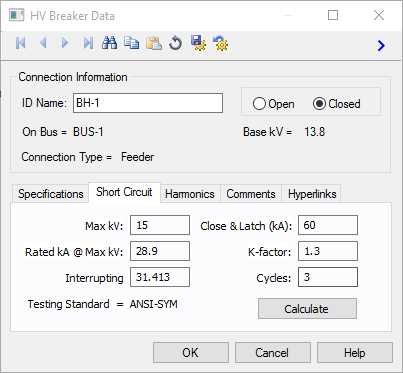
Figure 2: Short Circuit Tab

Option Description
Max kV Maximum voltage for which the breaker is designed and the upper limit for operation.
Rated kA @ Max kV Rated interrupting kA of the breaker at the breaker’s maximum voltage.
Interrupting (kA) Interrupting rating of the breaker.
Close & Latch (kA) Close & latch rating of the breaker.
K-factor Ratio of rated maximum voltage to the lower limit of the range of operating voltage in which the required symmetrical and asymmetrical interrupting capabilities vary in inverse proportion to the operating voltage.
Cycles Interrupting time of the breaker in cycles.
Testing Standard

The data in the library for the breaker is applicable for the specified test standard. The following testing standards are defined:

    • ANSI-TOTAL: The interrupting and momentary close & latch ratings are both in asymmetrical kA (total rms kA). Circuit breakers prior to 1964 used this test standard.
    • ANSI-SYM: The interrupting rating is in symmetrical kA whereas the momentary close & latch rating is in asymmetrical kA (total rms kA).
    • ANSI-Crest: The interrupting rating is in symmetrical kA whereas the momentary close & latch rating is in peak kA.
    • IEC: The circuit breaker ratings are as per IEC test standard.
Calculate

Fills in computed values for the Max kV, Rated kA @ Max kV, K-factor, Cycles, Interrupting, and Close & Latch fields, based on the device library entry for Mfr, Type, Style and the base kV. You can override these values by typing in different numbers. This button also causes the appropriate Testing Standard to be displayed for your information. (The Testing Standard comes directly from the device library and cannot be changed.)

Harmonics Tab

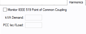
Figure 3: Harmonics Tab

Option Description
Monitor IEEE 519 Point of Common Coupling

EasyPower can monitor whether or not the IEEE 519 guideline for harmonics is met at the point of common coupling.

If selected, then the Harmonics Report indicates when this guideline is not being met.

kVA Demand The kVA demand.
PCC Isc/Load The ratio of short circuit current to load current at the point of common coupling.

Other Tabs

See Common Tabs for information on the Location, Comments, Hyperlinks, Media Gallery, or Collected Data tabs.

More Information

Database Technical Reference Common Tabs
Media Gallery  
     

www.easypower.com

EasyPower, LLC

7730 SW Mohawk St.

Tualatin, OR 97062

(503)655-5059

techsupport@easypower.com

feedback@easypower.com

EasyPower knowledge base

EasyPower Version 9.8

Copyright © 2017 EasyPower, LLC. All Rights Reserved.

Help was last updated on 7/10/2017