
This dialog box includes the following areas and tabs:
Figure 1: Connection Information
This tab lists connection information for the functional group. See Relay Controlled Fuse Groups and Relay Controlled Fuse Group Settings for more information.
| Option | Description |
|---|---|
|
ID Name |
Uniquely identifies the relay controlled fuse group. This name can be up to 16 characters long. The names default to RCFG-1, RCFG-2, RCFG-3, and so on, as you enter new groups on the one-line, but you can change those names to make them more descriptive if needed. |
|
Group Name |
The name of the relay controlled fuse group, which comes from the ID Name for the group. This name appears as a reference in the data dialog boxes of other required equipment items in the group. |
|
Group Type |
The type of relay controlled fuse group. This type appears as a reference in the data dialog boxes of other required equipment items in the group. |
This tab lists relay information for the functional group. See Relay Controlled Fuse Groups and Relay Controlled Fuse Group Settings for more information.
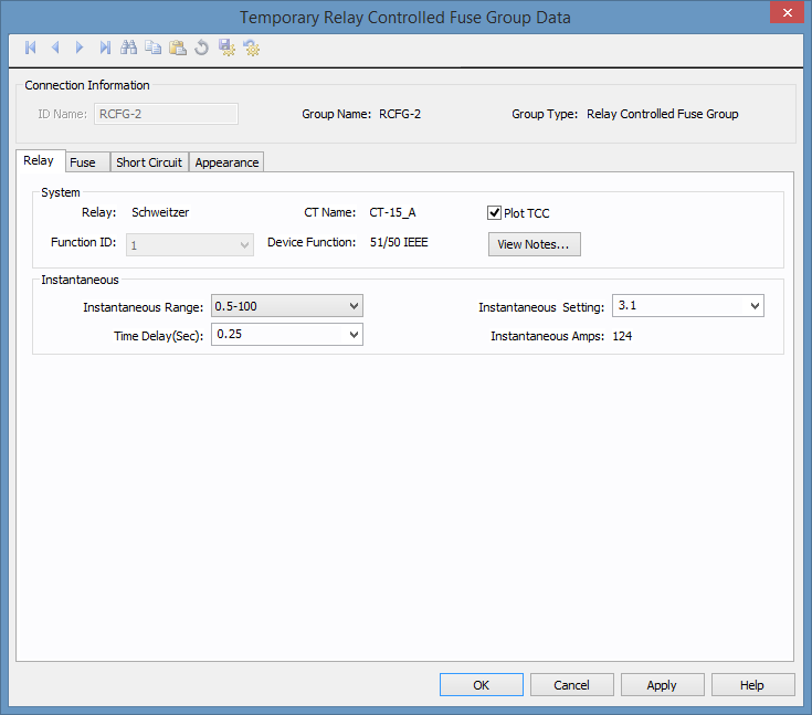
Figure 2: Relay Tab
| Option | Description |
|---|---|
|
System |
|
|
Relay |
The manufacturer for the relay. |
|
CT Name |
The name of the current transformer (CT) in the functional group. |
|
Plot TCC |
Indicates whether the relay information should be plotted on the TCC. |
|
Function ID |
The function ID for the relay function. |
|
Device Function |
The device function for the relay. See Relay Device Functions for information about device functions. |
|
View Notes |
Click to view notes recorded in the library for the device. Information may include data sheets or manufacturer's information for the device or assumptions needed to model the device. |
|
Instantaneous |
|
|
Instantaneous Range |
Provides a list of ranges of instantaneous pickup values applicable to the relay. The Instantaneous settings available depend on the Instantaneous Range selected. |
|
Instantaneous Settings |
The instantaneous pickup setting. |
|
Instantaneous Amps |
The instantaneous pickup current. |
|
Time Delay (Sec) |
Time delay for instantaneous trip. |
This tab lists fuse information for the functional group. See Relay Controlled Fuse Groups and Relay Controlled Fuse Group Settings for more information.
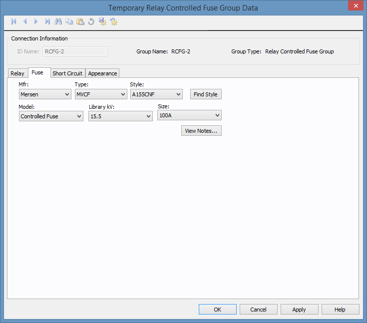
Figure 3: Fuse Tab
| Option | Description |
|---|---|
|
Mfr |
The manufacturer for the fuse. |
|
Type |
Fused switch types available from the manufacturer chosen in the Mfr field above. For a fuse to be available to a relay controlled functional group, it must be set up correctly in the device library. See Relay Controlled Fuse Group Settings for more information. |
|
Style |
Fused switch styles available from the type chosen in the Type field above. For a fuse to be available to a relay controlled functional group, it must be set up correctly in the device library. See Relay Controlled Fuse Group Settings for more information. |
|
Find Style |
Enables you to search the library for a fuse style. |
|
Model |
Fused switch model available from the style chosen in the Style field above. For a fuse to be available to a relay controlled functional group, it must be set up correctly in the device library. See Relay Controlled Fuse Group Settings for more information. |
|
Library kV |
Choose the section of the library the fuse data is entered. In most cases, the selected Library kV is approximately the base kV of the fuse. For LV fuses, this field is blank. |
|
Size |
This field enables you to view available sizes of the fuse model that you have selected and select a specific size. |
|
View Notes |
Click to view notes about the fused switch. You must first select a manufacturer, type, and style. The notes come from the device library. |
This tab lists short circuit information for the functional group. See Relay Controlled Fuse Groups and Relay Controlled Fuse Group Settings for more information.
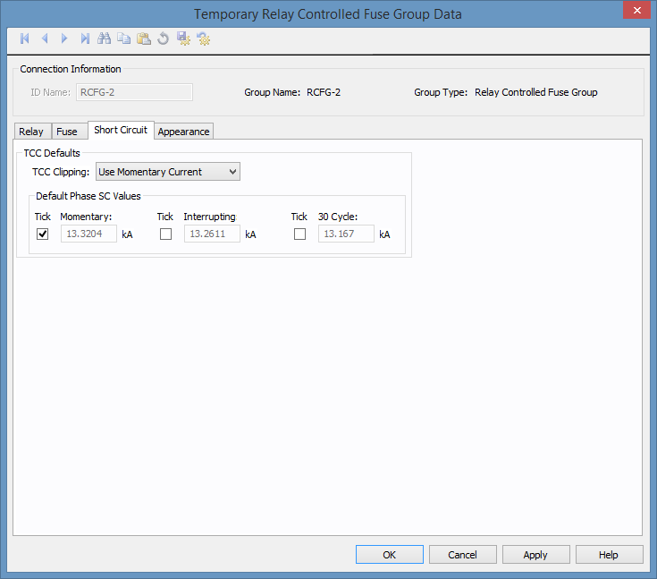
Figure 4: Short Circuit Tab
| Option | Description |
|---|---|
| TCC Clipping | You can clip the time current curve (TCC) for the breaker at the specified current in kA for Momentary (1/2 cycle), 5-cycle or 30-cycle. Select <None> to avoid clipping of the TCC. |
| SC Tick Marks |
Select the appropriate check boxes to display the tick mark on the TCC plot. You can display Momentary, Interrupting and 30 Cycle short circuit values. Enter the corresponding short circuit values in kA in their respective edit fields for phase short circuit. Note: These settings are only used if User-Specified is selected in Coordination Options > General > Default TCC Short Circuit Currents. Otherwise, the values are automatically calculated. |
| Default Phase SC Values |
The short circuit values entered in kA in these fields can be displayed for phase currents on TCC plots. Note: These settings are only used if User-Specified is selected in Coordination Options > General > Default TCC Short Circuit Currents. Otherwise, the values are automatically calculated. |
This tab lists appearance information for the combined relay and fuse curve in the functional group. See Relay Controlled Fuse Groups and Relay Controlled Fuse Group Settings for more information.
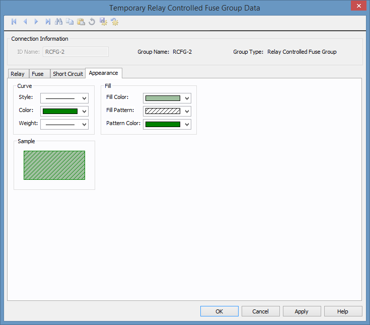
Figure 5: Appearance Tab
| Option | Description |
|---|---|
|
Curve |
Select the Style, Color, and Weight for the curve. This controls how the combined relay and fuse TCC curve appears when you plot the TCC. |
|
Fill |
Select the Fill Color, Fill Pattern, and Pattern Color for the curve. This controls how the combined relay and fuse TCC curve appears when you plot the TCC. |
| Temporary Data Dialog Boxes | |
| Functional Groups | |
| Plotting Functional Groups |
|
|