The layout options affect the way your one-line model is displayed when you use the Auto Layout feature. There are separate options for vertical and horizontal equipment spacing. The numbers indicate the spacing in grid points. A graphic diagram illustrates the spacing you are defining.
Nota: The graphic diagram is for illustrative purposes only, and does not adjust when the spacing is changed.
The initial values for Grid Spaces are derived from the layout options file selected in File Locations. There, you can choose from default, compact, or extended layouts. Ver Pestaña de Ubicaciones de Archivos para más información.
You can also change the numbers here. If you change the number here, it updates the selected layout options file with your custom values.
These layout options are also used as the initial spacing values when you manually place items on the one-line.
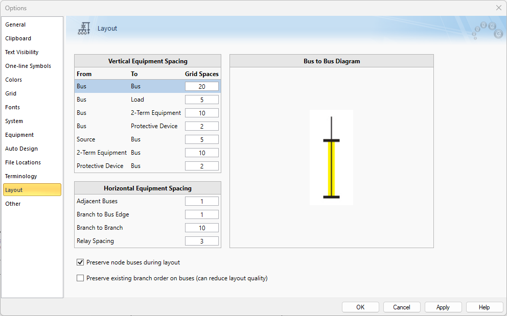
Figura 1: Layout tab of the Options Dialog Box
| Opción | Descripción |
Diagram |
|---|---|---|
|
Vertical Equipment Spacing (in grid spaces) |
||
|
From Bus / To Bus |
The vertical distance from one a bus to a bus. |
|
|
From Bus / To Load |
The vertical distance from a bus to a load. |
|
|
From Bus / To Protective Device |
The vertical distance from a bus to a protective device. |
|
|
From Source / To Bus |
The vertical distance from a power source to a bus. |
|
|
From Protective Device / To Bus |
The vertical distance from a protective device to a bus. |
|
|
Horizontal Equipment Spacing (in grid spaces) |
||
|
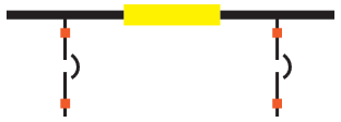
Adjacent Unconnected Buses |
The horizontal spacing between two adjacent unconnected buses. |
|
|
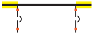
Branch to Bus Edge |
The horizontal spacing between the branch to the edge of a bus. |
|
|
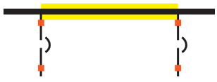
Branch to Branch |
The horizontal spacing between two branches. |
|
|
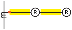
Relay Spacing |
The horizontal spacing between two relays. |
|
|
Additional Options |
||
| Preserve node buses during layout | This option enables you to choose whether to keep existing bus nodes as nodes (with a bus width of zero), or to allow these nodes to be resized automatically during auto layout.
|
|
| Preserve existing branch order on buses (can reduce layout quality) | This option enables you to choose whether to preserve the order of branches on buses which can reduce layout quality, or instead to disregard the order of branches on buses and let the layout calculations determine the optimal placement.
|
|