This section describes where you can input parameters for load calculations for various types of equipment.
Cargas
You can enter load data in the following equipment types: load, motor, panel, MCC, and tool point of connection. These are described below.
Carga
You can enter the rated load for the equipment in the Load Data dialog box on the Specifications tab. Various units are supported. The total load in the equipment is considered for load calculations. The total load for any load equipment is referred to as the connected load. Connected load calculations consider active power and reactive power separately during summation.
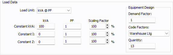
Figura 1: Load Data on the Specifications Tab
Other parameters are:
-
Demand Factor: This reflects the reduction in actual load being consumed compared to the connected load. The demand factor is used in calculating the demand load. The parameter does not affect the calculations for the connected load, the code factor load, or the design load.
-
Code Factors: This is the name of the load category based on the NEC or similar standards. Once you specify this parameter, the program looks up the code factor table to determine two factors: demand and code multiplier. The code factor table is in the device library or in the File Properties dialog box on the Code Factors tab. In the device library, the section called Demand Load contains the NEC based factors. Code factors are a type of demand factor based on NEC, applied on the aggregate load.
-
Quantity: This is the number of items for the specified load. The NEC demand factors for any category can be based on aggregate kVA or aggregate quantities of downstream equipment. The quantity-based demand factor is also defined in the same table as the code factor table.
Motor
You can enter the rating of the motor in HP or kW in the Motor Data dialog box on the Specifications tab. The motor’s kVA rating is handled differently depending on the type of calculation. The connected kVA is calculated by applying the power factor, efficiency, and HP-to-kW conversion.
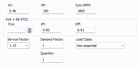
Figura 2: Input Parameters in the Motor Data Dialog Box on the Specifications Tab
-
Demand Factor: Demand kVA is calculated by multiplying the connected kVA by the demand factor.
-
The code factor field does not exist in the motor dialog. The program has two categories for motors: the largest motor, and others. The code factor table includes the multipliers. The code factor table is in the device library or in the File Properties dialog box on the Code Factors tab. For code factor calculations, the motor kVA is calculated using the full load amps (FLA) from the NEC tables for motors. There is support for three-phase and single-phase motor FLA tables in the program that is based on the NEC standard.
Panel
In the Description tab of the Panel Data dialog box, for each panel row, you can enter the load value in Amps or VA units, the power factor, and the demand factor. These input fields are similar to what is described for load equipment. These values affect the connected load and demand load calculations. For each row you can specify the load type as Load or Motor. There is also an input for Code Factors and Quantity. Code Factors is used to select the category of load based on NEC. The demand factors and multiplying factors for each category are defined in the code factor table. Any row with motor data is treated as motor loads for calculations.
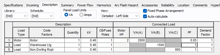
Figura 3: Input Parameters on the Panel Data Dialog Box on the Description Tab
CCM
In the Description tab of the MCC Data dialog box, for each MCC row you can enter the load value in Amps or VA units, the power factor, and the demand factor. These input fields are like what are described for load equipment in the previous section. These values affect the connected load and demand load calculations. For each row you can specify the load type as Load or Motor. There is also an input for Code Factors and Quantity. The Code Factors input is used to select the category of the load based on the NEC standard. The demand factors and multiplying factors for each category are defined in the code factor table.

Figura 4: Input Parameters on the MCC Data Dialog Box on the Description Tab
Punto de Conexión de Herramienta
The Description tab of Tool Point of Connection data dialog box has entry fields for full load amps (FLA), power factor (PF), and Demand Factor. The FLA is used to calculate the kVA. Connected load calculation considers active power and reactive power separately during summation. Demand load applies the demand factor to the connected load. Since a tool point of connection is a special type of load, code factor calculations simply apply a multiplying factor of 1.25.

Figura 5: Input Parameters on the Tool Point of Connection Data Dialog Box on the Specifications Tab
Barra
In the Bus Data dialog box on the Specifications tab, you can specify the Bus Type. When the bus type is set to Switchgear, Switchboard, or Panelboard, the program displays a tab that is named based on the bus type. The Diversity field is available on this tab.
The range for diversity is between 1 and 10. The load on the upstream side of the bus is calculated by dividing the total load on the bus by the diversity factor. There is also a checkbox to enable the load summary spreadsheet for the bus. The Calculate Downstream Load button updates the calculations including the loads from downstream buses.

Figura 6: Input Parameters on the Bus Data Dialog Box on the Switchgear/Switchboard/Panelboard Tab
Global Input Parameters
Options: General
In Tools > Options > General, there is an option named Use per phase basis for Code Factor kVA calculations: When the checkbox is clear, the demand factors in the code factor table are applied on the total load in all phases. When the checkbox is selected, the demand factors in the code factor tables area applied on the load on individual phases. This is the conservative approach for highly unbalanced loading among phases.

Figura 7: General Options for Code Factor kVA Calculations
Options: System
Downstream load is calculated at output side of a UPS: This option is found in Tools > Options > System. When the checkbox is selected, the load on the output side of the UPS is transferred to the input side. When the checkbox is clear, the input side assumes the rating of the UPS as the load.
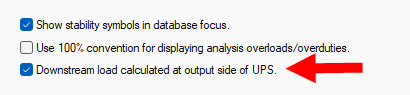
Figura 8: System Options for Downstream Load Calculations
Options: Equipment
The Design factor is a multiplier to oversize equipment to account for future load increases. You can set this value in Tools > Options > Equipment.
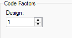
Figura 9: Equipment Option for Code Factor Design
Code Factors Tables
In File Properties
Code factors tables can be used from either the device library data or from the File Properties. If you use the table in File Properties, you can import a default set of data from the library. You can customize the code factors table.
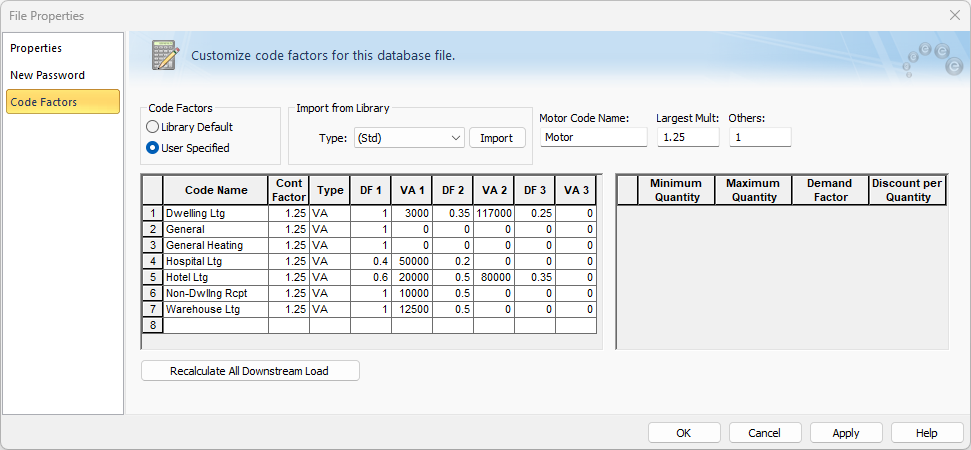
Figura 10: File Properties - Code Factors
|
Columna |
Descripción |
|---|---|
| Code Name | This column is used for adding your category. Equipment data dialog boxes such as load or panels will display the categories from this table. |
| Cont Factor | This column is for the multipliers used for continuous loads. |
| Tipo |
This column is to specify whether the demand factors are based on VA or quantity of similar categories. |
| DF1, DF2, DF3 |
These represent the demand factor for each level of VA aggregate load. |
|
VA1, VA2, VA3 |
These are the maximum differential aggregate loads in each level. |
When the Type is Quantity, you can enter data in the quantity table on the right side. The columns show per the selected Code Name on the left side table. The column descriptions are described in the table below.
|
Columna |
Descripción |
|---|---|
| Minimum Quantity | You can have different demand factors based on the quantity. The minimum quantity is the lowest quantity per group for which the demand factor applies. |
| Maximum Quantity | This is the largest quantity for which the demand factor applies. |
| Factor de Demanda | This is the demand factor that is applicable for the group or row. |
| Discount per Quantity |
This is a special case of diminishing demand factor per unit increment in quantity, also referred to in the NEC standard as "minus."’ An example is the NEC table for electric clothes dryers in dwelling units. This table has a row with the range of quantities between 12 and 23, and with the demand factor of 0.47. For each additional unit above 11, the aggregate demand factor is reduced by 0.01 (or 1%). So, the value entered here will be -0.01. Nota: Enter the discount as a negative number in this table. |
In the Device Library
The Load Calculations are found in the device library under Demand Load.
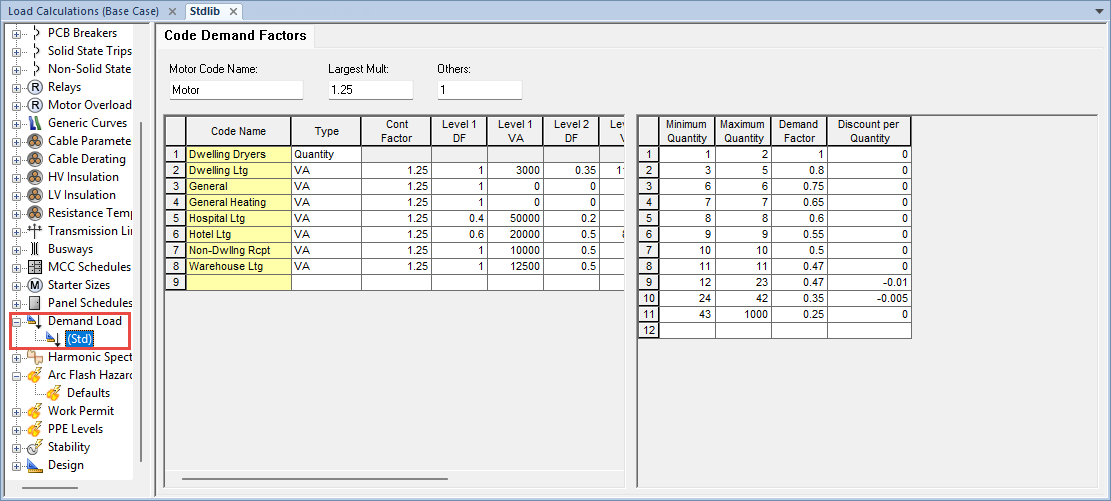
Figura 11: Load Calculations in the Device Library