This topic describes new EasyPower features and enhancements and bug fixes that are included in the release.
Características y Mejoras
Multiple Application Instances
New Selection Behavior Options
Data Verification Enhancements
Nota: Las funciones de la nueva versión a menudo incluyen cambios en la base de datos. Esto puede afectar a lo que ve en el Navegador de Base de datos y también lo que se incluye al exportar datos a archivos CSV. Si sus procesos de trabajo existentes se basan en información de la base de datos, asegúrese de revisar sus procesos después de actualizar el software.
New Import Data Feature
EasyPower 2026 introduces a new CSV-based import workflow that lets you modify existing one-line data or create new one-lines from formatted files, accelerating model building and large-scale updates. EasyPower validates the data and generates an import results report showing statistics, warnings, and old versus new values with direct links to affected equipment.
This release significantly improves EasyPower’s suitability for large-scale electrical system modeling, data-driven workflows, and cross-team collaboration by:
-
Expanding CSV import/export coverage
-
Enforcing data integrity through validation and reporting
-
Reducing risk through backups and warnings
These enhancements are particularly valuable for users managing complex facilities or migrating data from various sources. Highlights of this feature are described below. For additional information, see Import Data into EasyPower.
Import from the Database Browser
You can perform imports from the Database Browser by clicking Import on the Database Browser menu.
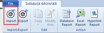
Figura 1: Import from the Database Browser Menu
Import from the File Menu
You can perform imports from the File menu by clicking File > Import > Import Data.
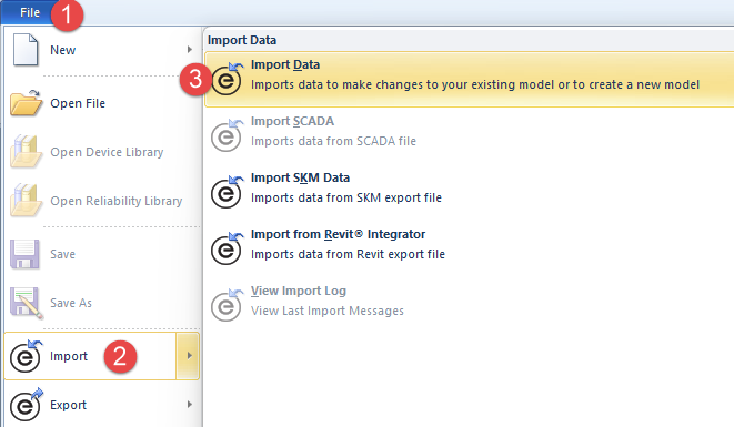
Figura 2: Import from the File Menu
Multiple Import File Types Supported
EasyPower now supports importing data using three formats:
-
Combined EasyPower CSV
-
Individual EasyPower CSV files
-
Zipped Individual CSV files
This provides flexibility when receiving data from internal and external teams.
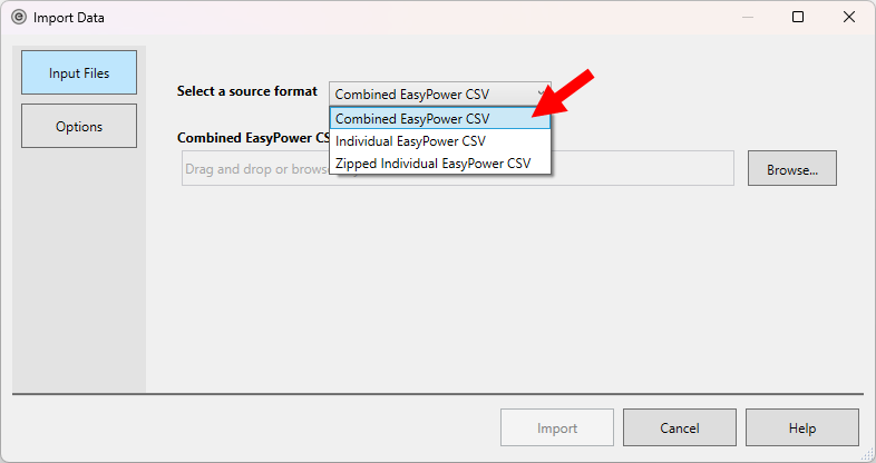
Figura 3: CSV Import File Formats
Import Options and Validation Reports
Before finalizing an import, users can configure how EasyPower handles:
-
Blank values
-
Equipment that exists in the model but not in the import file
-
Missing equipment in the input files
-
Auto layout behavior for new or all equipment
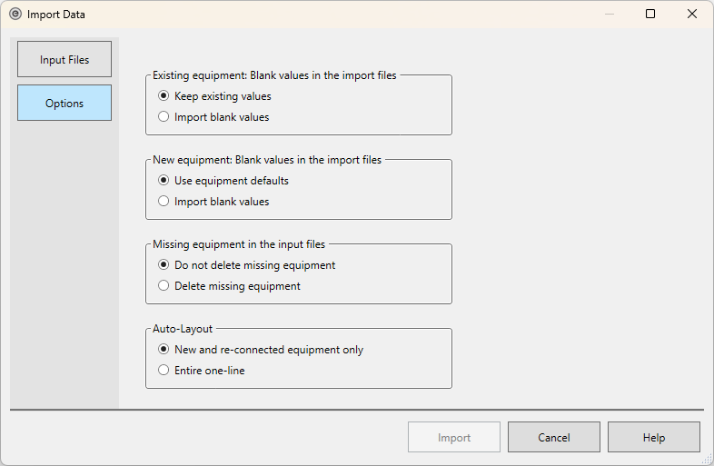
Figura 4: Import Data Options
After processing, EasyPower displays an Import Results report showing:
-
Statistics
-
File backup location
-
Advertencias
-
Applied changes
Users can save the text and accept changes or undo the import.
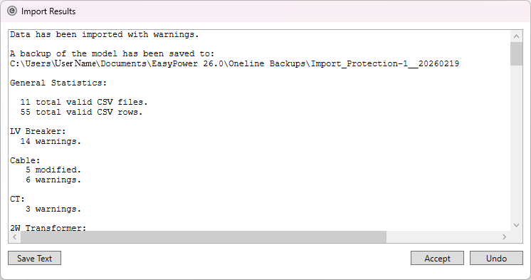
Figura 5: Resultados de Importación
At the end of the import, a final Import Results Report is displayed showing old and new values, with the ability to go to each equipment item on the one-line or to open and edit the equipment item's data.

Figura 6: Informe de Resultados de Importación
Automatic Backup Protection
Before any import operation, EasyPower automatically creates a backup of the existing model file. Backup details are recorded in the import log. You can specify the backup location in File Locations.
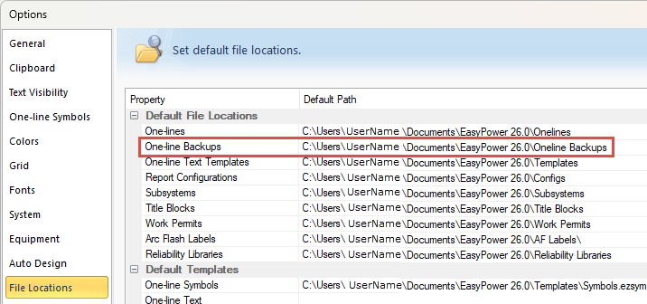
Figura 7: One-line Backups Location
Supported Equipment Types
The import system supports structured CSV imports for a wide range of electrical equipment, including:
-
Variador Ajustable de Frecuencia
-
Interruptor de Transferencia Automática (IAT)
-
Batería
-
Barra
-
Electroducto
-
Cable
-
Condensador
-
Current-Limiting Reactor
-
Transformador de Corriente
-
Filtro
-
Interruptor con Fusible
-
Generador
-
Interruptor-automático de AT
-
Inversor
-
Carga
-
Interruptor-automático de BT
-
CCM
-
Metro
-
Motor
-
Panel
-
Fotovoltaico
-
Rectificador
-
Derivación
-
Interruptor
-
Three-Winding Transformer
-
Two-Winding Transformer
-
Línea de Transmisión
-
Servicio-eléctrico
-
Zigzag Transformer
-
UPS
Each equipment type includes:
-
Strict column name matching
-
Defined data types
-
Expected value ranges or lists
-
Automatic clipping of out-of-range numeric values
The use of these CSV files reduces import errors and improves model consistency.
Ver Supported Import Fields para más información.
Future Enhancements
The import features are being released in phases. In the initial phase, the following items cannot be imported:
-
Single-phase equipment
-
Relés
-
Groups (relay controlled fuse groups)
-
Tools (within points of connection)
-
DC equipment (although DC connections can be imported)
-
Internal panel and MCC equipment rows (such as internal breakers, motors, or loads). However, existing connections to panel and MCC equipment rows are not broken during import.
We plan to add these items in future releases.
Note Regarding Import Connectivity Processing
The import engine evaluates connectivity columns (From Bus, To Bus, Device IDs, etc.) to build network relationships. However, if ID Names are changed in the same import file that modifies connectivity, results may be inconsistent. We recommend that you import ID name changes in a separate file first, and then import connectivity changes in a separate file afterward.
Enhanced Export Data Feature
The export functions have been enhanced to better support bidirectional CSV workflows, making it easier to share data, perform round-trip updates back into EasyPower, and to integrate with external programs. The release includes exportable CSV templates in addition to customizable export configurations to standardize data collection.
Export from the Database Browser
You can export existing data from within the Database Browser. If you first select items on the one-line before opening the Database Browser, only those items will be included in the export. If nothing is selected, then all items in the one-line are included.
Nota: As a result of this change, the Open With Excel and CSV buttons have been removed and replaced with the Export button.
Several configurations are available for determining what data will be exported. You can choose from preselected configurations or create your own using the Report Configuration option. Initially, you may want to try using the Importable Data configuration to get accustomed to the configuration layout.
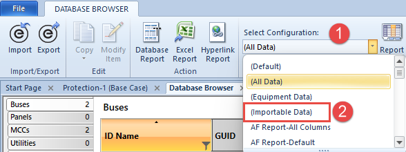
Figura 8: Select Configuration
After selecting items and opening the Database Browser, click Export.
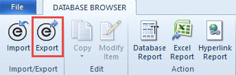
Figura 9: Export on the Database Browser Menu
You can then select whether you want to export to a combined or individual CSV file, and provide information for the folder path or file name. Ver Flexible Export File Options para más información.
Nota: As part of this effort, some existing configurations have been renamed. Configuration files that include "Columns" in the name now use "Data" instead. For example, All Columns is now All Data.
Export from the File Menu
You can also export existing data directly from the File menu. When you export from the File menu, all items in the one-line model are exported.
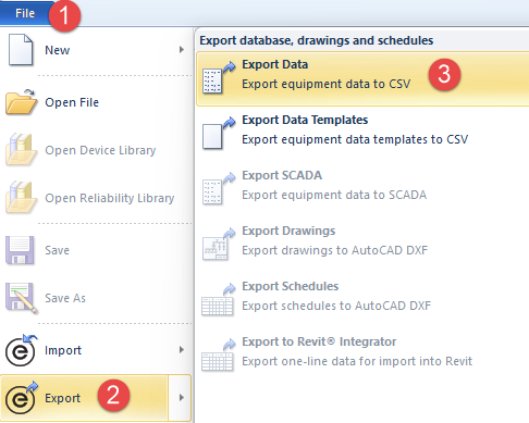
Figura 10: Export Data from the File Menu
You can then select whether you want to export to a combined or individual CSV file, and provide information for the folder path or file name. Ver Flexible Export File Options para más información.
In addition, you have the option to select an existing configuration or to edit a configuration to create your own custom configurations. Custom configurations can be reused to support specific workflows or project data needs.
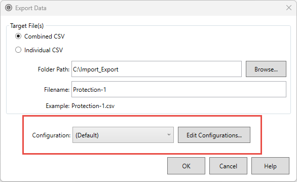
Figura 11: Export Data Dialog Box
Flexible Export File Options
You can export model data using two distinct CSV strategies, depending on your needs:
-
A Combined CSV file, which simplifies sharing:
-
A single CSV file containing all equipment types.
-
Each equipment type is separated by a header row followed by its data.
-
-
Individual CSV files, which improve filtering, sorting, and integration with scripting or data science tools:
-
One CSV file per equipment type (bus, cable, breaker, transformer, etc.).
-
Files are automatically separated by EasyPower based on the file name.
-
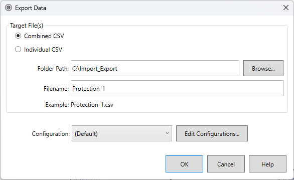
Figura 12: Export Data to CSV Dialog Showing Combined vs. Individual CSV Selection
Nota: We suggest you try using the (Importable Data) configuration as a starting point for exporting information that you intend to edit and then import back into EasyPower.
Export Data Templates
You can export blank CSV templates for populating new equipment data. This enables you to perform data collection outside of EasyPower and to standardize data entry across teams. Templates can be generated as combined or individual CSV files and using configurations, just like the other export CSV files.
To export data templates, from the File menu, click Export > Export Data Templates.
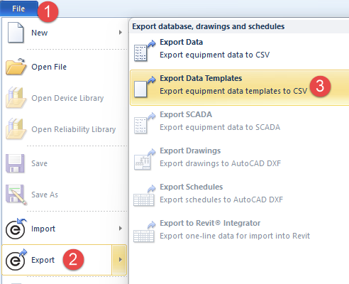
Figura 13: Export Data Templates
Note Regarding Excel Data Conversions
There are some additional considerations needed regarding using Excel for CSV file import and export.
-
Prior to importing or exporting, review the automatic data conversion options in Excel to prevent issues. These options are found in Excel by clicking File > Options > Data > Automatic Data Conversion. See Control Data Conversions in Excel for more information.
-
In addition, you may need to review your Short Date settings in the Windows Time & Language options to ensure that dates with slashes are not being used.
Note Regarding the Auto-Calculate Option
Imported values are ignored when the Auto-calculate checkbox is selected in the equipment data dialog boxes to automatically calculate field values.
New Auto Layout Feature
The new Auto Layout feature automatically arranges equipment on one-line diagrams using user-defined spacing rules to reduce overlaps and minimize manual cleanup when creating, importing, or refining models. Auto Layout eliminates the manual work of positioning, arranging, and aligning components across an entire one-line diagram, a selected area, or newly imported equipment. Use this feature in your one-line models, TCCs, and drawings to improve and standardize your graphic presentations. This feature can also be used to improve the layout of imported data.
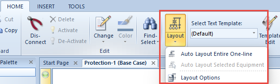
Figura 14: Layout Button on the Home Tab
Key Capabilities
Auto Layout can be applied in the following scenarios:
-
An entire one-line diagram
-
Selected equipment on an existing one line
-
Imported equipment, for both new and existing one lines
In all cases, placement is determined by the settings defined in the Layout options.
Layout Modes
You can layout an entire one-line or selected equipment on the one-line. You can also perform auto layout on imported equipment.
Auto Layout Entire One Line
You can apply Auto Layout to all equipment on a one-line from the Home tab by selecting Auto Layout Entire One Line with no items selected. A warning is displayed to indicate that the full diagram layout will be affected before proceeding.
Alternatively, if no items are selected and you click the Layout button, this also displays the warning and then performs auto layout on the entire one-line.
Auto Layout Selected Equipment
Auto Layout can also be applied to a subset of equipment:
-
Select items by dragging a selection rectangle, then choose Auto Layout Selected Equipment from the Home tab.
-
Use Select Downstream to automatically select all equipment on a branch, then apply Auto Layout to the selected items. You can either use the Layout menu as shown above, or select the option from the right-click menu.
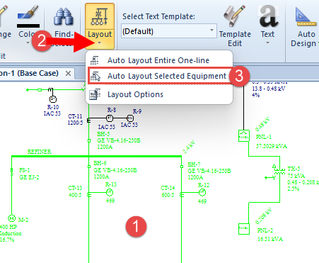
Alternatively, if you select items and then click the Layout button, this performs auto layout on the selected items.
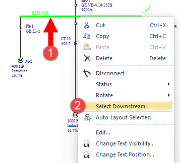
Figura 15: Select Downstream
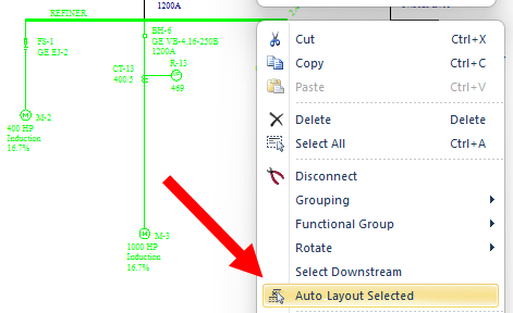
Figura 16: Auto Layout Selected
Auto Layout Imported Equipment
When importing data, Auto Layout behavior is controlled from selections made in the Options tab. Layout can be applied to:
-
Newly imported and reconnected equipment only, or
-
The entire one line
This enables users to control how imported data integrates with existing layouts.
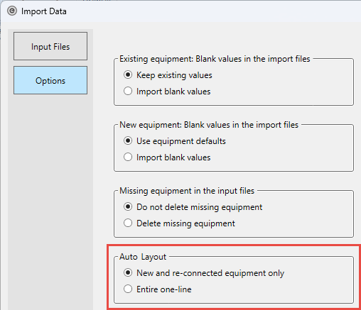
Figura 17: Auto Layout Options When Importing Data
Layout Options
Use Options to configure grid spacing. You can also select from default, compact, or expanded configurations.
Configurable Grid Spacing
The Layout tab in the Options dialog box controls how Auto Layout positions equipment. The program provides separate settings for vertical and horizontal spacing, defined in grid spaces. A diagram illustrates the spacing relationships for reference.
Nota: The diagram is illustrative only and does not change dynamically when spacing values are modified.
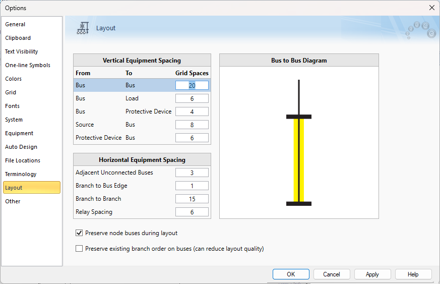
Figura 18: Layout Options Dialog Box
You can choose to preserve node buses (with a width of 0) or to allow nodes to be resized automatically.
You can also choose to preserve the existing branch order or to instead disregard the order of branches on buses and let the layout algorithm determine the optimal placement. Note that preserving the existing branch may reduce the layout quality.
Nota: The spacing options selected here also affect the initial spacing when you manually insert equipment onto a one-line.
Layout Options Files
There are three Layout Options files available to select in Tools > Options > File Locations.

Figura 19: File Location for Layout Options Files
Estos incluyen:
-
Default Layout Options.ezlyt
-
Compact Layout Options.ezlyt
-
Expanded Layout Options.ezlyt
You can choose any of the files to modify how close or far apart equipment items are when you use Auto Layout.
Nota: If you make changes to the numbers in the Layout tab, it overwrites the contents of the file selected in File Locations with your changes.
Auto Layout in TCCs
You can perform Auto Layout in TCCs. This includes the ability to auto layout the entire TCC one-line or selected equipment, and the option to use the existing one-line layout.
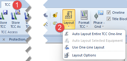
Apply Auto Layout to New TCCs Option
In the Coordination Options on the General tab, there is a new setting to Apply auto layout to one-line in new TCCs. When this option is selected and a new one-line is created for a TCC, the auto-layout settings are automatically applied.
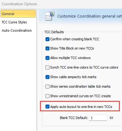
Figura 21: Apply Auto Layout to One-line in New TCCs
Auto Layout in Drawings
You can perform Auto Layout in drawings. This includes the ability to auto layout the entire drawing or selected equipment.
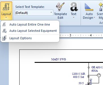
Figura 22: Auto Layout Options in Drawings
Multiple Application Instances
EasyPower 2026 now supports running multiple application instances at the same time, enabling you to work on different one-line models and their related reports in parallel. This improves productivity for users performing multiple studies, comparing alternatives, or moving information between models, without the need to close and reopen files. To support this experience, tabs for the one-line and reports are enabled by default within each instance.
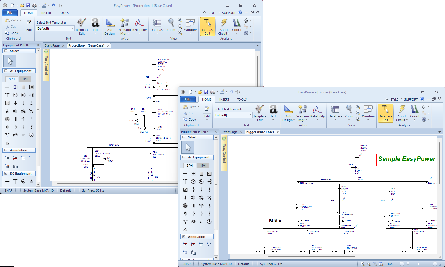
Figura 23: Multiple Instances of EasyPower Open at the Same Time
Tab Options On Top By Default
Due to the ability to have multiple instances, you can now select tabs to view the one-line model and reports within the instance. The Tab Location can be set to Top or Bottom in System > Tools > Options on the General tab.
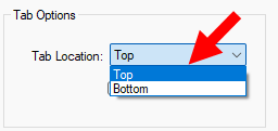
Figura 24: Tab Location
Tabs enable you to easily switch between the one-line view and various reports.
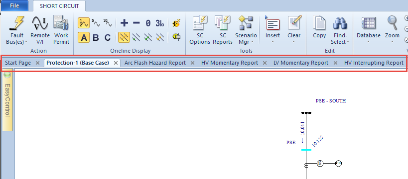
Figura 25: Tabs in the EasyPower Session Window
Close and Exit Changes
The File menu has been reorganized with revised Close and Exit options.
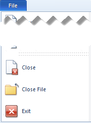
Figura 26: Close, Close File, and Exit on the File Menu
Las opciones son las siguientes:
-
Close: Closes the active document. For example, if you have multiple reports open and one is selected, the command closes only the selected report.
-
Close File: Closes the active file. For example, if you have a .DEZ file and several reports open, this command closes the .DEZ file and all the reports, but does not close the EasyPower program.
-
Exit: Closes the active file and reports and also closes the EasyPower program.
New Selection Behavior Options
A new dual-direction selection mode gives you more precise control when using your mouse pointer to select items on the one-line, aligning selection behavior with common CAD conventions. When the option is selected, dragging left-to-right selects only equipment entirely within the selection area; dragging right-to-left selects all equipment the selection boundary crosses. This makes it easier to target specific equipment in dense diagrams and reduces rework caused by accidental over-selection.
You can enable this option by clicking Tools > Options > General, and then selecting Enable dual direction selection mode.
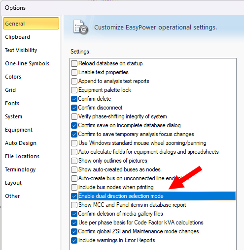
Figura 27: Enable Dual Direction Selection Mode Option
When enabled, dragging left-to-right selects only items fully contained within the selection rectangle, while dragging right-to-left selects items that cross through the selection area. See the examples below:
Example 1: Dragging left to right (note that the cable and bus, parts of which extend beyond the selection area, are not selected):
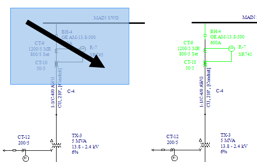
Figura 28: Dragging Selection Left-to-Right
Example 2: Dragging right to left (note that for the cable and bus, parts of which extend beyond the selection area, are selected):
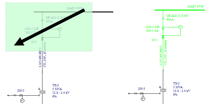
Figura 29: Dragging Selection Right-to-Left
New Select Downstream Feature
The new Select Downstream feature speeds up analysis and editing by automatically selecting all equipment downstream of a chosen item, making it easy to work with an entire branch of the model.
Examples of when you might use this feature include:
-
Generate TCCs
-
Run faults
-
Perform auto layout
-
Export data
Select Downstream Options
There are new options in System > Tools > General that control whether the selection traverses through open breakers or deactivated equipment.
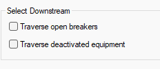
Figura 30: Select Downstream Options
Select Downstream Menu
To use this feature, use the mouse pointer to select the topmost item in a branch, and then right-click and from the menu, click Select Downstream.
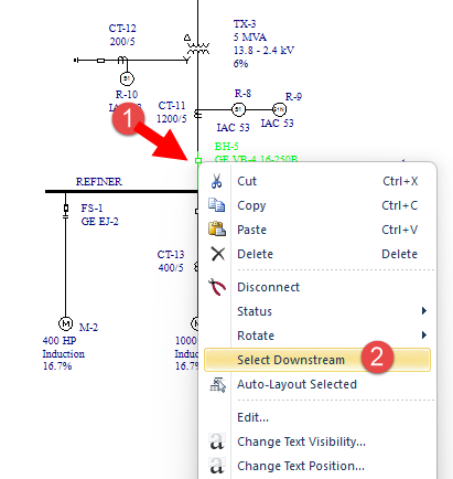
Figura 31: Select Downstream Option
All items downstream of the topmost item are selected.
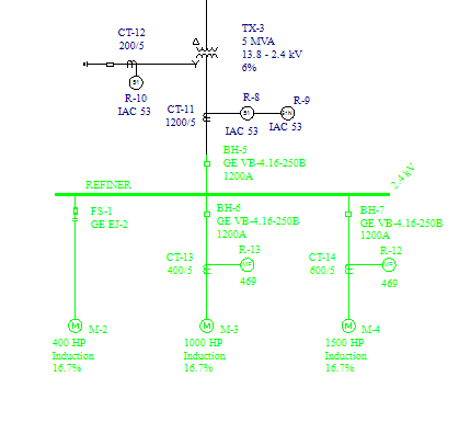
Figura 32: Downstream Items are Selected
You can now perform other functions on the selected items.
Select Downstream When Performing Find-Select
This feature is also available from the Find-Select menu after you select an item on the one-line.
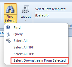
Figura 33: Select Downstream from Selected
Data Verification Enhancements
The Verify Data button on the Tools offers improved data validation and identification of missing equipment data. This button consolidates the functions previously done by the Verify Library Data and Verify OL Data buttons.
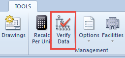
Figura 34: Verify Data Button
When you use this feature, the One-line Verification Report provides additional details.
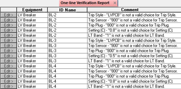
Figura 35: One-Line Verification Report
Assessment Date
In File Properties, you can specify an assessment date. This date is saved with the file and is used to fill the new Assessment Date variable on arc flash labels. The default arc flash labels have this new variable included. If you have created your own custom labels, you can add the variable to include the assessment date. This supports the new mandate in the 2026 National Electric Code (NEC).
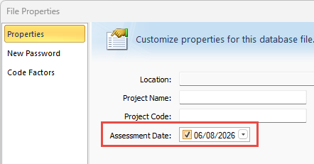
Figura 36: Assessment Date in the File Properties Dialog Box
When printing arc flash labels, the program initially uses the Assessment Date from File Properties if one has been entered but you can override it.
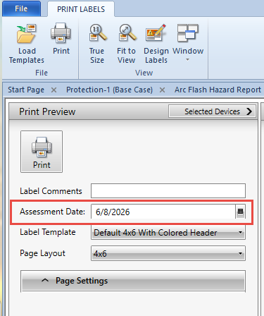
Figura 37: Assessment Date in Print Preview
There are new variables that you can add to your custom arc flash labels.
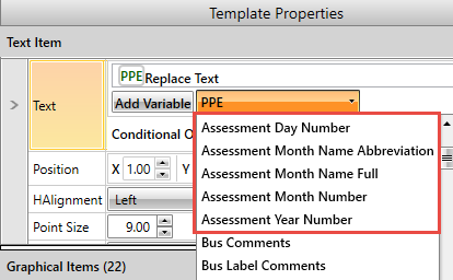
Figura 38: Assessment Date Variables in Label Designer
These variables replace the original "Arc Flash Analysis..." variables.
|
Old Variable Name |
New Variable Name |
|---|---|
| Número del Día de Análisis de Arco Eléctrico | Assessment Day Number |
| Abreviatura del Nombre de Mes de Análisis de Arco Eléctrico | Assessment Month Name Abbreviation |
| Nombre Completo de Mes de Análisis de Arco Eléctrico | Assessment Month Name Full |
|
Número de Mes de Análisis de Arco Eléctrico |
Assessment Month Number |
|
Número de Año de Análisis de Arco Eléctrico |
Assessment Year Number |
Text Visibility Enhancements
New installations of EasyPower are set up with global text visibility turned on for all equipment and data. This is to better display the information for importing and exporting data. This only applies to brand new installations on a computer where EasyPower has never been installed. Existing installations display text as they did in prior versions. Text visibility settings are now stored in a shareable .ezvis file that can be used to share settings across users and computers.
You can control the global text visibility using the options in Tools > Options > Text Visibility, as you could do before. If you have versions prior to EasyPower 2026 installed on your computer, your existing options are preserved and will be applied to any existing and new one-lines.
When you make changes to the global text visibility in Tools > Options > Text Visibility, the changes are stored in a file with the extension .ezvis. The location of this file can be viewed or modified in Tools > Options > File Locations next to Text Visibility Options.
-
For computers with prior version EasyPower installations, the file name is displayed as Saved Text Visibility Options.ezvis.
-
For computers without prior version EasyPower installations, the file name is displayed as Default Text Visibility Options.ezvis.


Nota: On computers with prior EasyPower versions installed, both the Default and Saved versions of the file are installed. The path is set to the Saved file after installation. You can select the Default file instead if you prefer.
Because these settings are now stored in a file, it is now possible to have a shared .ezvis file on a network drive, which enables you to share the settings across different computers and users.
Start Page Enhancements
The Start Page has been streamlined to provide a cleaner entry point into EasyPower. The new layout lets users get to common actions faster and focus on opening files and starting work.
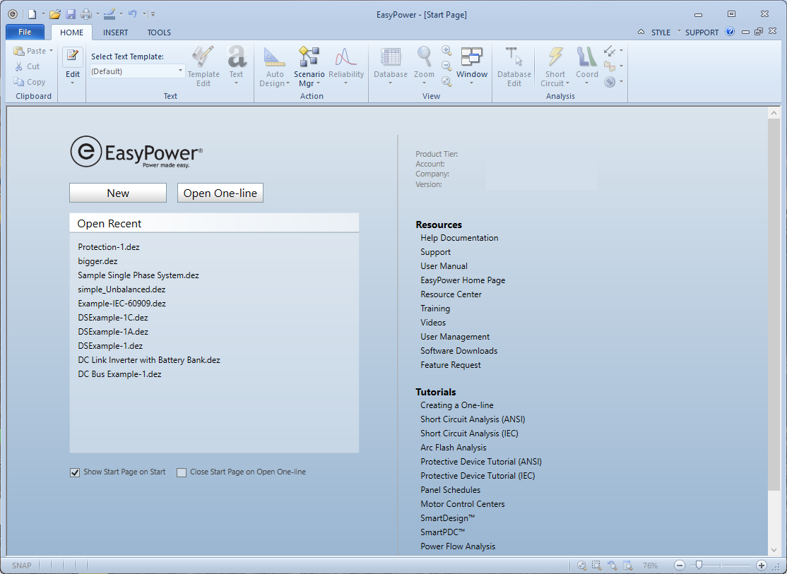
Figura 39: La Página de Inicio
Simplified Installation
The installation processes have been simplified and ensure consistency with other Bentley Systems products. This streamlines deployment and helps users and IT teams complete upgrades with fewer steps and a more predictable setup process.
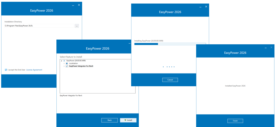
Figura 40: Installation Dialog Boxes
Expanded Device Library
EasyPower 2025 adds over 2,000 new manufacturer-specific devices to the device library.
Support for Revit 2026
EasyPower 2026 adds support for Revit 2026 to keep BIM-based electrical design workflows current. This includes support for spare breakers, the new cable core type parameter, and Revit’s removal of support for magnetic raceway for cables.
Miscellaneous Enhancements
-
External Unique ID on the Comments Tab: On the Comments tab of each equipment data dialog box, there is a new External Unique ID field. This represents the unique identifier for the equipment item of up to 64 characters and is used to match an item to a corresponding item in an external program, such as asset management software.
-
External Unique ID Variable for Work Permits: There is a new variable called {EXTID} that you can use to display the External Unique ID on your work permits.
-
U.S. Unit Consistency: The Unit field for cables, busways, and transmission lines now uses "U.S." instead of "US" to match other types of equipment and to improve import results.
-
ZSI Tab on LV Breaker Data: The ZSI tab in the LV Breaker Data dialog box has been reorganized to better represent the option grouping on that tab.
-
SmartDesign: References to SmartDesign have been updated to refer to Auto Design so that it is consistent within the product and the documentation.
-
MCCB Default Class: For low voltage breakers, the default Class is now set to MCCB instead of LVPCB.
Correcciones de Errores
Arco Eléctrico
-
Resolved an issue where arc flash results were not shown on the one-line diagram when performing analysis using the option Both (Including & Excluding Main) with the Momentary method (correct results were shown in the Arc Flash Hazard report, however).
-
Resolved an issue where performing an arc flash analysis on a single-phase bus and then confirming the Short Circuit Options dialog box without making any changes caused branch flow results to be displayed.
-
Resolved an issue where arc flash boundary and incident energy results were inconsistent when motor contributions changed state.
-
Resolved an issue where arc flash label hazard units were displayed incorrectly as plain text (cal/cm2 or J/cm2) instead of using the proper superscript format.
Coordinación
-
Resolved an issue where the trip amp value displayed in the TCC note for low-voltage breakers (including Multi 9 and Multi 9 [IEC] types) was rounded to a whole number instead of showing the actual value specified in the Breaker Data dialog box.
-
Resolved an issue where notes in a TCC displayed incorrect short time and instantaneous breaker settings.
-
Resolved an issue where the TCC plot curve did not start at 0.001 seconds as specified in the device library for certain styles of LV breaker.
-
Resolved an issue where when plotting LV breaker time-current curves, the program incorrectly displayed zone selective interlocking curves and settings for the short-time delay.
-
Resolved an issue where the instantaneous section of TCC curves extended beyond the bottom of the plot graph due to insufficient library data.
-
Resolved an issue where the arcing current tick mark in TCC plots displayed incorrect text when using the Integrated method with IEEE 1584-2018. The tick mark label always showed “100% Arcing Current” even when the reduced arcing current was used for arc flash calculations.
-
Resolved an issue where the thermal section of certain Square D low voltage breakers plotted incorrectly in TCC curves when using both low and high instantaneous settings, resulting in inaccurate instantaneous amp values.
-
Resolved an issue where the short-time section of Square D Micrologic Std LX low voltage breakers plotted incorrectly when the short-time delay was set to a maximum value of 0.5 and the long-time delay was set to a minimum value of 2.
-
Resolved an issue where EasyPower closed unexpectedly when opening or printing a stored TCC in instances where items had been deleted from the TCC.
-
Resolved an issue where the magnetic section of MCCB time-current curves did not display correctly when used with certain motor overload styles, resulting in inaccurate curve representation and crossing behavior due to insufficient data points in the motor overload curve.
-
Resolved an issue where Siemens MCCB curves did not display correctly in TCC plots when motor overload was present.
-
Resolved an issue where the short-time delay section of low voltage breaker TCC plots displayed incorrectly when long-time delay was set to 0.5 and specific short time and instantaneous pickup settings were used.
-
Resolved an issue where the ground fault curve in TCC plots displayed incorrectly as a vertical line when viewing single line-to-ground conditions due to duplicate description entries causing the wrong data row to be selected.
-
Resolved an issue where the instantaneous section of a low voltage breaker TCC curve extended horizontally beyond its valid data range. The curve improperly continued due to a gap between opening and clearing sides, instead of clipping at the maximum defined current.
-
Resolved an issue where EasyPower closed unexpectedly when inserting a Siemens SST breaker after deleting a previously inserted Siemens MCCB breaker in a TCC when required class information was left unspecified.
-
Resolved an issue where reopening a stored ground TCC with phase trip disabled resulted in a “curves not fully specified” error and prevented the curve from being displayed.
-
Resolved an issue where fuse curves were not displayed when reopening a stored TCC plot. Although the Plot Phase TCC setting remained enabled, the fuse curve would not appear until the fuse dialog box was reopened and confirmed.
-
Resolved an issue where, after storing and reopening a TCC containing multiple chained relays, the graphic representation of a downstream relay could display incorrectly on the TCC one-line.
-
Resolved an issue where changes to the maintenance instantaneous pickup value in a breaker's temporary dialog within the TCC one-line were not reflected in the TCC plot. The curve continued to display the minimum maintenance value, and the Maint Inst value was not shown in the note unless a different breaker style was selected.
-
Resolved an issue where plotting certain motor control centers could cause EasyPower to close unexpectedly.
-
Resolved an issue where EasyPower could close unexpectedly when entering the Coordination focus in models containing circuit breakers that were not configured.
-
Resolved an issue where TCC grid size was determined from the system registry instead of the DEZ file settings, resulting in inconsistent grid sizing.
-
Resolved an issue where EasyPower closed unexpectedly when deleting an inserted relay curve in a TCC plot.
-
Resolved an issue where incorrect curves were plotted in a TCC when the long-time delay band fell within certain ranges.
Navegador de Base de datos e Informe
-
Resolved an issue where selecting a configuration in a localized version of EasyPower and then selecting the default configuration caused the program to display an error message.
-
Resolved an issue where, when the Show MCC and Panel items in database report option is selected (in Tools > Options >General), opening and navigating MCC equipment in the Database Browser caused the program to display inconsistencies in the Motors tab, including missing rows and incorrect motor counts.
-
Resolved an issue where open database reports did not update when switching between scenarios. Report titles and displayed data (such as transformer sizes) continued to reflect the previously loaded scenario instead of the active one.
-
Fixed a typographical error in the "SLG Interrupting X/R" column name on the SC Report-3PH & SLG configuration.
-
Resolved an issue where DC utilities configured with a fault unit of Amps were incorrectly displayed as kA in the Database Browser.
-
Resolved an issue where cells for relay-level fields in the Database Browser (including Data Status, External Unique ID, and Comment) were incorrectly displayed as split across relay functions instead of merged, resulting in inconsistent formatting for relays with multiple functions. (Note that External Unique ID is new in EasyPower 2026).
-
Resolved an issue where when creating an Excel Report that included a note, the report displayed incorrect font size and lost fill color in the report header.
-
Resolved an issue where changing a low-voltage breaker from Solid State Trip (SST) to Non-Solid State Trip did not clear the previously configured short-time settings, causing outdated values to persist in the Database Browser.
-
Resolved an issue where saving a file while both a scenario and the Database Browser are open incorrectly flags one-line equipment as modified. This generates changes in the Scenario Changes report even though no actual changes were made.
-
Resolved an issue where the IEC generator RGf / X"d value appeared blank in the Database Browser and reports, even though the value was present in the Generator Data dialog box.
-
Resolved an issue where Amp Class values for two-winding transformers were not displayed in the Database Browser, CSV exports, or Excel reports.
-
Resolved an issue where the Testing Standard displayed inconsistently between the HV Breaker Data dialog box and the Database Browser.
-
Resolved an issue where the short time pickup I2T field displayed as blank in the Database Browser for low voltage breakers even though a value was set in the LV Breaker Data dialog box.
-
Resolved an issue where transmission line size values were duplicated due to an incorrect line size in the data import.
Biblioteca de Dispositivos
-
Resolved an issue where the MCC enclosure size values for the 1.000–5.000 range in the Device Library (Arc Flash Hazard > Defaults) were higher than the values defined in IEEE 1584-2018 Table G.18.
-
Resolved an issue where EasyPower allowed entry into Short Circuit analysis without a valid device library, despite displaying a warning, and then closed unexpectedly.
Dibujos
-
Resolved an issue where cable color, style, and weight changes made in the one-line did not update in drawings associated with the one-line.
-
Resolved an issue where drawings incorrectly displayed the full line for transmission lines, cables, and busways when the Show Entire Line option was not selected.
-
Resolved an issue where stored short circuit results did not display in equipment dialog boxes within drawings, with values (such as SC Sym kA on switchgear) appearing grayed out after storing results.
-
Resolved an issue where a box added in a drawing was incorrectly converted into a note after saving, closing, and reopening the file.
-
Resolved an issue where switching ATS sources via the context menu in drawings did not update the displayed fault current. The drawing continued to show the previous fault values after changing the source.
-
Resolved an issue where changes made in the device library were not saved when using the CTRL+S shortcut. The shortcut now works when focus is on the library tree view, but users may still need to use the Save icon when editing in the right pane to ensure changes are applied.
Estabilidad Dinámica
-
Resolved an issue where copying and pasting Dynamic Stability plot data excluded column headers, causing data to be transferred without context.
Elevations
-
Resolved an issue where descriptions and identifiers were missing when batch printing elevation views to PDF.
Equipo
-
Resolved an issue where the labels for the navigation tabs at the bottom of the MCC Data dialog Description tab were cut off due to scaling on high resolution monitors.
-
Resolved an issue that occured when the utility Fault Duty Unit was set to kA, where the X0/R0 value did not display in the one-line diagram due to the variable being missing from the default template.
-
Resolved an issue where the program closed unexpectedly when faulting a bus with a spare LV breaker that has short-time ZSI enabled.
-
Resolved an issue where changing the system units between U.S. and Metric did not consistently update motor data.
-
Resolved an issue where cable size units were incorrectly displayed on the one-line as AWG instead of kcmil when the cable size included a decimal value.
-
Resolved an issue where no validation message was displayed when a DC motor’s resistance value was outside the valid range.
Ubicaciones de Archivos
-
Resolved an issue where the File Locations settings could be unintentionally cleared when opening or closing the Options dialog box without accessing the File Locations tab, causing user-defined paths to be lost and replaced with default values.
Armónicos
-
Resolved an issue where performing a frequency scan on a new one-line produced incorrect impedance results on the first attempt. Re-running the frequency scan (after re-entering Harmonics) returned the correct values.
-
Resolved an issue where second- and third-order fundamental harmonic currents displayed incorrect results on the Harmonics tab of the Filters Data dialog box.
Notas
-
Resolved an issue where default note background color changes made in the Default Note Properties dialog box were not saved unless EasyPower was closed. After modifying the background color and applying the changes, newly inserted notes did not reflect the updated color, and reopening the dialog box showed the previous settings.
Diagramas-unifilares
-
Resolved an issue where the mouse pointer for switchgear was not visible on some 4K monitors when placing switchgear equipment from the Equipment Palette onto the one-line.
-
Resolved an issue where the program closed unexpectedly when deleting multiple pieces of equipment on a one-line diagram when there were incorrect connections on a drawing associated with the one-line.
-
Resolved an issue where invalid connections between both ends of a breaker and certain equipment types (2‑winding transformers, 3‑winding transformers, or UPSs) could cause the program to close unexpectedly when deleting buses.
-
Resolved an issue in the CL Reactor Data dialog box where the program displayed a “data is not complete” message but did not identify that the Impedance kVA field is a required field.
-
Resolved an issue where it was not possible to select a symbol on the one-line due to the margin around the ID Name box.
-
Resolved an issue where EasyPower closed unexpectedly when repeatedly opening the same file while the Equipment Palette is undocked.
-
Resolved an issue where short circuit variables used in one-line text Display Conditions were not correctly interpreted in templates, resulting in missing or blank variable references in custom one-line text templates. This also affected displayed text conditions.
-
Resolved an issue where breaker and fused contactors could only be rotated to 180 degrees, preventing rotation to other orientations.
Flujo de Potencia
-
Resolved an issue where motor starting analysis failed to solve and displayed a “possible zero impedance” error even when no zero impedances existed in the model. This occurred on systems with generators running on separate islands.
-
Resolved an issue where Power Flow could fail to solve when single-phase line-to-neutral loads were connected downstream of a delta-connected transformer, due to remote transformers incorrectly affecting the solution.
-
Resolved an issue where double-clicking an Automatic Transfer Switch (ATS) in the Power Flow focus caused the one-line display to revert to sequence view and omit voltage values, despite the ABCN display options being selected. The problem also prevented a full system update of power flow results when toggling certain 1-phase ATS configurations.
Portuguese
-
Fixed multiple inconsistencies in the Portuguese user interface menus, including standardizing shortcut keys, aligning inconsistent menu wording, and restoring missing options across all applicable menus.
Para Imprimir
-
Resolved an issue where the Filename field was blank when printing Short Circuit, Power Flow, and Harmonics Error Reports using the Microsoft Print to PDF option.
Revit
-
Resolved an issue where symmetrical fault current values were not exported to Revit, resulting in blank EasyPower Symmetrical Fault Current fields in Revit.
-
Resolved an issue where importing panel load values from Revit produced incorrect values if the EasyPower panel load unit was set to Amps instead of VA.
Scenario Comparison Reports
-
Resolved an issue where Equipment Duty Scenario Comparison reports incorrectly displayed IEC header columns instead of ANSI for Overdutied Devices when viewing the report in Print Preview.
-
Resolved an issue on the Arc Flash Scenario Comparison report where single-phase bus results were omitted when the bus name matched an ATS name.
-
Resolved an issue where Scenario Comparison Reports remained open in Print Preview after closing the associated .DEZ file, and where closing multiple reports could cause EasyPower to terminate unexpectedly.
-
Resolved an issue where creating and then immediately deleting an Equipment Group in the Manage Equipment Groups dialog box caused a persistent error message that repeated with any interaction until the dialog box was closed and reopened.
-
Resolved an issue where ANSI Equipment Duty Scenario Comparison reports displayed incorrect IEC column headers in both the Print Preview and exported PDF files when the Worst/Best Scenario and Overdutied Devices options were selected.
-
Resolved an issue where EasyPower closed unexpectedly when generating an Equipment Duty Scenario Comparison report after promoting a scenario to the base case under certain conditions.
Informes
-
Resolved an issue where the Equipment Duty Report returned blank results for DC buses when bracing values were present.
Cortocircuito
-
Resolved an issue where EasyPower closed unexpectedly when entering the Short Circuit focus if a transmission line had an R0 value of zero, due to handling of zero or near-zero sequence impedance values.
-
Resolved an issue where incident energy was not calculated in version 2025 when the upstream trip device had no settings specified, but had been calculated in version 2024 under the same conditions.
-
Resolved an issue where EasyPower closed unexpectedly when entering the Short Circuit focus if a transmission line had an R0 value of zero.
-
Resolved an issue where buses defined as Junction Box – Large were incorrectly highlighted in red on the one-line diagram even when incident energy was below the defined threshold.
-
Resolved an issue where single line-to-ground fault currents in utility data that were significantly larger than the 3-phase values displayed NaN ("Not a Number") values in the one-line diagram instead of the calculated short circuit currents.
-
Resolved an issue where induction generators did not contribute to short circuit calculations, resulting in incorrect bolted fault currents at buses.
-
Resolved an issue where EasyPower closed unexpectedly when performing a short circuit analysis after switching the calculation method from IEC to ANSI in cases involving induction generators.
-
Resolved an issue where voltage-based filtering in the Short Circuit Options did not correctly fault certain buses when the voltage included a decimal.
-
Resolved an issue where EasyPower could close unexpectedly during short circuit analysis when active relays were connected to deactivated CTs.
-
Resolved an issue where the IEC HV Breaking Report displayed zero values in the Duty Amps DC time constant column when performing single-line-to-ground, double-line-to-ground, or line-to-line faults on non-standard fault phases.
-
Resolved an issue where the program failed to store short circuit results when running analysis for an entire system.
-
Resolved an issue where users were unable to enter the Short Circuit focus due to an “incomplete HV breaker data” error due to the application interpreting blank default values as invalid.
-
Resolved an issue where remote bus voltage values did not update on the one-line when units where changed.
-
Resolved an issue where EasyPower closed unexpectedly when attempting to enter Short Circuit analysis for a specific project.
-
Resolved an issue where voltage mismatch conditions were not consistently detected during short circuit analysis when single-phase validation occurred.
Subsistemas
-
Resolved an issue on the Insert menu Subsystem toolbar where large subsystem templates failed to load and displayed an invalid subsystem error.
Text Templates
-
Resolved an issue where the default DC load text templates displayed amperage without proper spacing.
Plantillas de Bloque de Título
-
Resolved an issue where title block images referenced by only the file name were not displayed in the main one-line print preview or output.