Notes on AFD
Power Flow Modeling
For the AFD power flow simulation, the motor on the output of the AFD will respond in its loading dependent upon the output frequency and voltage. The modeling used in EasyPower is approximated based on a typical 100 HP motor response to these factors, with the motor load on the shaft modeled as speed squared.
For output frequencies below system frequency, a drive will maintain constant Volts/Hz by dropping the voltage proportionally with the frequency. For output frequencies above system frequency, voltage is typically held constant, as there is no need to drop voltage since Volts/Hz drops as frequency increases. Additionally, you must be careful to consider that when operating a motor above system frequency, that it should be specified to accommodate the additional load at the highest frequency. As frequency increases, so does the load on the shaft, since we have elected to approximate behavior with a speed-squared load characteristic.
From the tables below, we see an interesting behavior. Because we are holding a constant Volts/Hz when below system frequency, the motor power factor is practically constant. Above system frequency, power factor improves. This happens because a motor rated for higher than system frequency operation is actually operating at a “lower” frequency than the nameplate of the specified motor. Thus, there is a drop in motor power factor.

Figure 1: Motor Tabulated Results for AFD Operating from 20 to 60 Hz
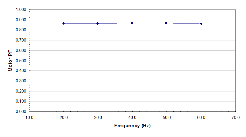
Figure 2: Plot of Motor pf vs. Frequency for AFD Operating from 20 to 60 Hz
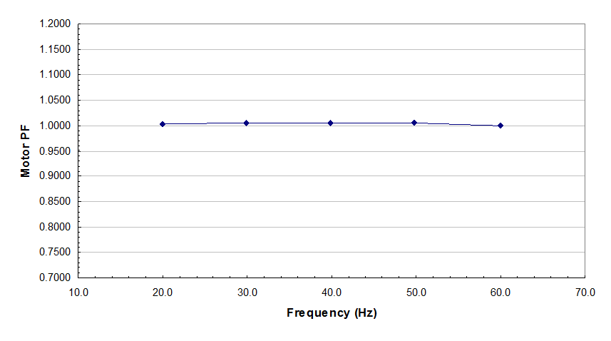
Figure 3: Plot of Correction to pf vs. Frequency for AFD Operating from 20 to 60 Hz
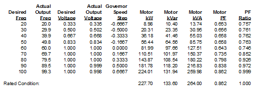
Figure 4: Motor Tabulated Results for AFD Operating from 20 to 100 Hz
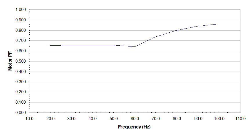
Figure 5: Plot of Motor pf vs. Frequency for AFD Operating from 20 to 100 Hz
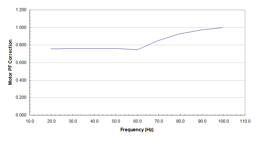
Figure 6: Plot of Correction to pf vs. Frequency for AFD Operating from 20 to 100 Hz
And so, the tables and plots above show a clear relationship between motor power factor and AFD output frequency. These results are used to generate general relationships that apply corrections to motor pf in EasyPower as a motor on an AFD output has a frequency specified different than system base frequency. In addition, consider the next table where we have shown motors specified for increasing maximum frequency of operation. We see that increasingly higher HP ratings are needed to satisfy the greater power requirement at higher AFD frequency outputs. These results assume:
- The motor is fully loaded at 60 Hz such that a higher rated motor is needed to supply the additional load as load torque increases by the square of the speed.
- The initial motor HP rating is 100 HP.
- The motor cannot have its terminal voltage increased above rated nameplate voltage.
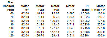
Figure 7: Rated pf and HP for Greater Than 60 Hz AFD Operation
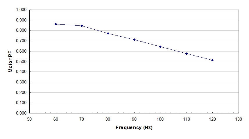
Figure 8: Plot of pf at 60 Hz vs. Frequency as We Increase Motor HP to Accommodate Increased Loading
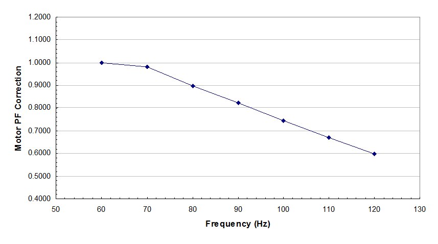
Figure 9: Plot of pf Correction at 60 Hz vs. Frequency as We Increase Motor HP to Accommodate Increased Loading
Thus, from our results, it is clear that below system frequency, we do not need to make any corrections to motor power factor, but for frequencies above system frequency, we need to consider:
- Motor HP rating.
- The much lower power factor at system frequency for a motor with a nameplate speed higher than system frequency.
- The increase in motor power factor as increase speed from system frequency up to the maximum frequency of the motor.
The plot below takes this into consideration for our typical 100 HP motor, and presents the corrections needed with a curve fit equation used to simulate this action. The corrections from this plot are used in EasyPower to simulate the increased frequency effects on AFD motors.
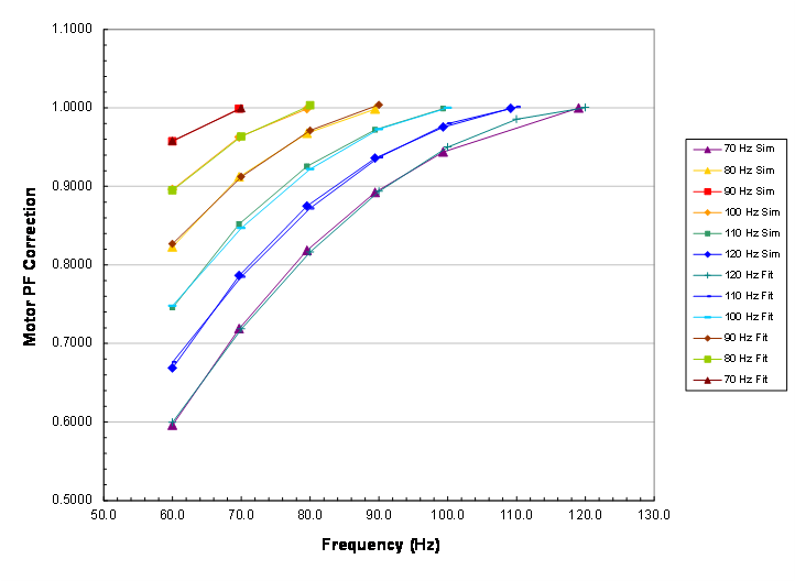
Figure 10: Correction to motor pf when specified with over-frequency capability
The best way to read the plot above is to look at one curve in relation to a given AFD motor application. If we have an AFD and need to operate its motor at say, a maximum frequency of 100 Hz, then we first select the aqua curve set that has its highest correction value of 1.0 at 100 Hz. If the motor specified for this application has a rated speed of 100 Hz (i.e. an actual speed of 1800 RPM for 60 Hz and a rated maximum speed of 3000 RPM at 100 Hz) then if the motor were actually running at 60 Hz, its power factor would be about 0.75 times the motor’s rated power factor. If it were running at 80 Hz, the motor’s power factor would be about 0.92 times the motor’s rated power factor.
More Information
| AFD Data |

|