AFD Data
This dialog box includes the following areas and tabs:
See Common Tabs for information on the Location, Comments, Hyperlinks, or Collected Data tabs.
See also: Notes on AFD
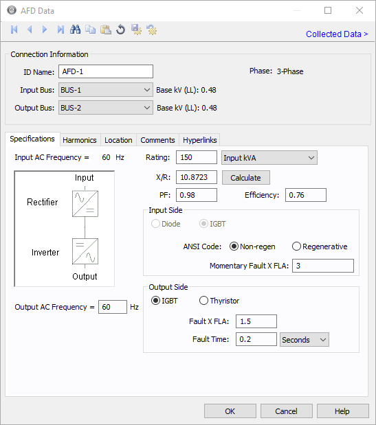
Figure 1: AFD Data Dialog Box
Connection Information
| Option | Description |
|---|---|
| ID Name |
Uniquely identifies the equipment item. The program automatically assigns a name, but you can change it, if needed. The name can be up to 16 characters long. For adjustable frequency drives, the program automatically assigns the names AFD-1, AFD-2, AFD-3, and so on. |
| Input Bus |
ID name of the bus on the input side of AFD. The base kV of the bus is shown on the right. |
| Output Bus |
ID name of the bus on the output side of AFD. The base kV of the bus is shown on the right. |
|
Phase |
The phase of the item. Currently, this is for reference only. |
Specifications Tab
| Option | Description |
|---|---|
| Input AC Frequency | The fixed frequency on the input side. This is specified in the System tab of Options dialog box. |
| Output AC Frequency | The adjustable frequency on the output of the AFD. This affects the frequency of all equipment connected on the output of the AFD. |
| Rating | Rated Input kVA or the motor HP of the drive. |
| X/R | If the AFD is regenerative, this value is used to define the short circuit X/R ratio of the contribution delivered at the input of the AFD. The Calculate button uses an ANSI standard lookup table to fill in this value. |
| PF | The input power factor of the AFD for power flow simulations. |
| Efficiency | The efficiency of the AFD. This creates a real power increase from the output to the input of the AFD. |
| Input Side | |
| Diode / IGBT | This is currently IGBT only. |
| ANSI Code | Select Non-regen to simulate a non-regenerative drive and Regenerative to simulate a regenerative drive (which includes a short circuit contribution on the input of the AFD). |
| Initial / Momentary Fault x FLA | The defined bolted fault level for the input of the AFD if it is regenerative. The label displayed is based on the IEC or ANSI option selected to Tools > Options. |
| Output Side | |
| IGBT / Thyristor | Select IGBT to model a source inverter on the output, or choose Thyristor to model a Thyristor output. This currently does not affect any calculations. |
| Fault x FLA | The fault current output of the AFD under a bolted fault condition. |
| Fault Time | The time that Fault x FLA is produced by the AFD under fault conditions |
Harmonics Tab
Use the Harmonics tab to indicate whether this equipment item is introducing harmonics into your power system.
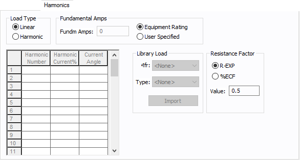
Figure 2: Harmonics Tab
| Option | Description | |||||||||||||||||||||
|---|---|---|---|---|---|---|---|---|---|---|---|---|---|---|---|---|---|---|---|---|---|---|
| Load Type |
The default is Linear, indicating the equipment does not produce harmonics. Choosing Harmonic makes the item an harmonic source and makes other fields in this tab available to edit. Note: For an adjustable frequency drive (AFD), the Load Type is always Harmonic. |
|||||||||||||||||||||
| Fundamental Amps |
Use to set the fundamental amps. The options are as follows:
To use fundamental current calculated by power flow, select Calculated from Power Flow in the Summation Fundamental Voltage area of the Harmonics Options > Control dialog box. |
|||||||||||||||||||||
| Harmonic Spreadsheet |
Use the spreadsheet to enter the harmonic spectrum produced by this item. You can enter up to 30 different harmonics in each equipment item. In the spreadsheet, enter the Harmonic Number (such as 5 for the 5th harmonic), the Harmonic Current in percent of the Fundamental Amps, and the Current Angle. By indicating the current angle, you can simulate transformer phase shift effects on rectifiers so appropriate canceling can take place. The harmonic may be integer or non-integer. |
|||||||||||||||||||||
| Library Load |
Common harmonic spectra may be entered from the device library. For instructions on how to enter your own spectra information, see Harmonics with Spectrum™. After selecting a particular device library spectrum from the Mfr and Type lists, click Import, and that spectrum is entered into the harmonic spreadsheet. |
|||||||||||||||||||||
| Resistance Factor |
EasyPower offers two methods for calculating RH:
RH = RFund * H R-EXP RH = RFund * (1+ECF*H2)/(1+ECF) EasyPower defaults all skin effect correction to R-EXP and a value of 0.5.
|
Other Tabs
See Common Tabs for information on the Location, Comments, Hyperlinks, or Collected Data tabs.
More Information
| Database Technical Reference | Common Tabs |
| Notes on AFD | |
| Media Gallery |
|
|