Notes on Inverter Model
DC Rated kV
When simulating a DC system that connects to an AC system via an Inverter, then the proper Rated DC voltage needs to be specified for the Inverter. The DC voltage is related to the AC voltage under no load conditions as follows:
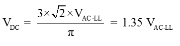
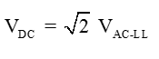
This equation is for a 6-pulse rectifier and includes the ripple on the DC bus, and is typically used on DC systems that do not include a large smoothing capacitor; systems such as HVDC and simple large rectifiers. If you know that the DC bus includes a DC bus capacitor, and that under loaded conditions ripple is minimal, you should use:
Mandatory Commutation Impedance
When an Inverter is specified as Thyristor, mandatory commutation impedance must be specified on the Power Flow tab. This impedance is used to calculate terminal conditions on the output of the Inverter according Kimbark’s Equations. In addition, we mandate a transformer be placed downstream of the Inverter that has the exact same impedance specification as the commutation impedance. This is the reason why the commutation impedance specification in the Power Flow tab is specified just like a transformer; so that there is a one-to-one correspondence. Kimbark’s equations have been written with a basis from high voltage DC lines, which always incorporate and isolation and voltage transformation transformer from the AC line voltage where the converter is specified, and the converter itself. Thus, to use the equations, there must always be a converter-transformer pair, or the equations are not correct for the model.
Power Flow Modeling
An Inverter source has three source control modes similar to the AC power flow source control modes. The control modes are:
- Stand Alone (i.e. SWING)
- Voltage Controlling (i.e. PV)
- Non-Voltage Controlling (i.e. PQG)
An Inverter also requires knowledge of rectifier behavior if a Thyristor type is specified; which includes the need for more data. That data is commutating reactance and firing angle min and max. Since Kimbark’s DC equations are written with Alpha for the rectifier and Gamma for Inverter, we will follow this convention, and require Gamma Min and Gamma Max limits be specified.
If you do not enter a commutation impedance matching an external inverter transformer, the DC bus voltage does not properly reflect the AC side bus voltage drop. This results in the DC Bus voltage being different than it actually would be if the commutation impedance had been included properly.
From several analysis efforts, we have come to realize that Kimbark’s equations are not perfect. Tests show they may not produce exactly the same kW on the AC side as seen on the DC side; an obvious violation of conservation of energy. If you note that you have set the efficiency of a Rectifier or Inverter to 100%, and notices that the kW values are slightly different, it simply is an issue of Kimbark’s equations supplying a very close approximation to the AC side power, versus an exact match for an ideal “lossless” converter.
Note also that Thyristor Inverters have their Type forced to be PQG, and that Q is not specified since Kimbark’s equations determine it.
Stand Alone Control Mode
In the Stand Alone control mode, the output of the Inverter is basically a SWING source. Thus, whatever DC source is on its input, needs to supply the load that the output of the inverter is forced to serve. This means that we could have conditions where the system doesn’t solve. Consider these conditions:
- We have a Battery, DC Gen or DC Util operating as unregulated sources. If the voltage drop on the input to the inverter is too severe, we could never reach a solution, as the Invert input load is constant power.
- A Photo-Voltaic is loaded incorrectly to cause its voltage to drop below VMP, thus creating a condition where its power must be dropped to hold its terminal current at ISC.
Under such conditions, we need the inverter to reduce its loading on the DC system.
Min Load Voltage Set Point
Due to the discussion in the previous section, it is clear (especially for Photovoltaics), that we need a method to reduce the specified load of the Inverter if we are creating a voltage collapse condition on the DC system. Thus, a feature was implemented that reduces the specified load until the DC voltage rises above the Min Load Voltage Set Point.
This feature works for Voltage Controlling and Non-Voltage Controlling modes, but does not function when in Stand Alone mode. In Stand Alone mode, we are required to satisfy the load on the AC output (i.e. it is a SWING). In this mode of control, no change to the load can be made, even if the DC input voltage is collapsing. And thus, we are led into the next section.
Min Solution Voltage Set Point – For Photovoltaics Only
Since a legitimate voltage collapse can occur on the input to the Inverter, we must cover for it and alert. We have thus implemented the Min Solution Voltage Set Point. However, this really is only a condition that will occur with a Photo Voltaic that is being loaded to a point where it drops voltage to maintain ISC on its output. And so, when the DC voltage on any Photo-Voltaic drops below this value, the solution is terminated, and you are informed that a solution cannot be reached due to issues with the loading of Photovoltaics.
Voltage Controlling Mode
In voltage controlling mode, the Inverter source is basically a PV generator with a specified real power output and control voltage set point. Var limits are active. If the input DC voltage drops below the Min Load Voltage Set Point, the specified real power is reduced until that set point is met. The source still controls voltage and includes var limits during this real power control action.
Non-Voltage Controlling Mode
In non-voltage controlling mode, the Inverter source is basically a PQ generator with a specified real and reactive power output. If the input DC voltage drops below the Min Load Voltage Set Point, the specified real power is reduced until that set point is met.
Islanding of DC Input
Due to the need for inverters to detect having their inputs offline, we have added island checking code that detects all islands. After every switching action, islands are detected and tagged. If the input to the Inverter is in an island without a SWING, the output source of the Inverter is taken out of service with an additional switching action and subsequent island check. This then allows us to remove the DC input to the Inverter, and its output will zero out.
Islanding of AC Output
Inverters also need to make sure that if the AC output is in an island with no SWING, that no load is placed on the DC input. If an island condition is created on the output of the Inverter, then the DC load draw on the input of the Inverter is zeroed out, and the DC system will not be loaded by the Inverter.
Load Reduction Deadband
This setting is used to help the solution solve quicker when Inverters are reducing their load to meet their Min Voltage kW Reduction Threshold (MVKWRT). In a condition where the input DC voltage to an Inverter drops below MVKWRT, we need to reduce the scheduled kW required on the DC side by the inverter. This is accomplished on each iteration using:
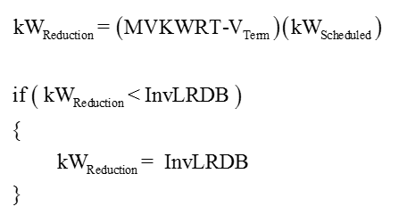
where InvLRDB is this registry variable.
Name: InvLoadReductionDeadband
Location: Options
Type: DWORD
Represents: Values in percent
Default: 5
Example: A value of 5 is 5% which is 0.05 pu in the engine.
More Information
| Inverter Data |
|
|