Three Winding Transformer Data
This dialog box includes the following areas and tabs:
- Database Dialog Box Toolbar
- Connection Information
- Specifications Tab
- Impedance Tab
- TCC Tab
- LTC (Load Tap Changer) Tab
- Harmonics Tab
See Common Tabs for information on the Location, Comments, Hyperlinks, or Collected Data tabs.
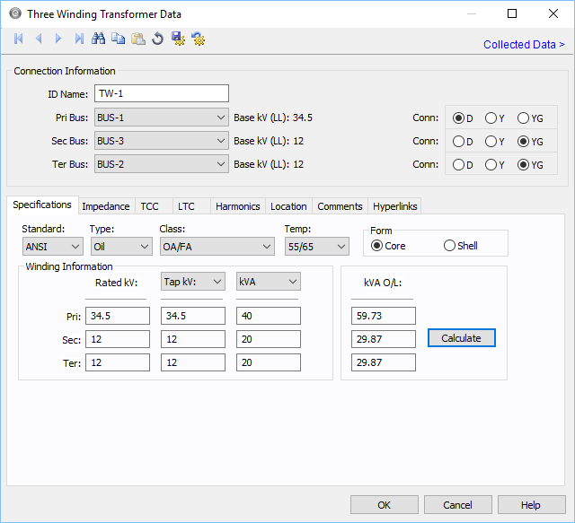
Figure 1: Three-Winding Transformer Data Dialog Box
Connection Information
Specifications Tab
| Option | Description |
|---|---|
| Type | Type of transformer (oil, gas, dry, silicone, or vapor). This field is used to determine the rating capacity of the transformer for the power flow overload solution. |
| Class | Type of cooling used by the transformer. Various combinations of forced air, water and forced oil are available. This field is used to determine the rating capacity of the transformer for the power flow overload solution. |
| Temp | ANSI temperature rating of the transformer. Various combinations can be chosen and are dependent upon the type of transformer. Dual ratings such as 55/65 increase the overload capability of the transformer by 12 percent. |
| Form |
Either core or shell type transformers can be selected. If Core is selected, the Z0% value on the Impedance tab is set to 0.85 of Z%. If Shell is selected, Z0% is equal to Z%. |
| Winding Information | |
| Rated kV | Rated kV of a winding. The rated kV can be different than the base kV or the tap kV. EasyPower automatically adjusts the model to account for different taps, turns ratio and bases you choose. |
| Tap kV / Tap% | Tap kV of a winding. You can also specify the tap kV in terms of percentage of the rated value. If the actual tap kV is not known, enter the rated kV. Load tap changer control can be used to determine final tap settings if desired. EasyPower automatically adjusts the model to account for different taps, turns ratio and bases you select. |
| MVA/kVA | Self cooled rating of the transformer. Use to select the unit in MVA or kVA. |
| MVA OL | The overload rating is based on the temperature and class ratings. It is filled in using the Calculate button or you can type in a different rating. |
Impedance Tab
Transformer impedance is in percent on the self-cooled MVA of the winding and nominal voltage rating. The strict definition is the percent of rated voltage impressed on the high voltage winding to produce rated full load current in the short circuited low voltage winding.
In this dialog box, Zps stands for Primary to Secondary, Zpt stands for Primary to Tertiary, and Zst stands for Secondary to Tertiary.
Manufacturers provide impedance data in many different formats depending on the test facility and transformer size. The data entry format for EasyPower was chosen from one of the most common testing procedures.
You can specify the impedances in any MVA base: the primary, secondary, or tertiary.
![]()
Figure 2: Impedance tab of Three-Winding Transformer Data Dialog Box
| Option | Description |
|---|---|
| R1 | Positive sequence winding resistance in percent. |
| X1 | Positive sequence winding leakage reactance in percent. |
| R0, X0 | Zero sequence winding leakage impedance in percent. If you don't know this value, enter the positive sequence impedance (Z) for shell transformers (see the Form field on the transformer's main dialog box). For core transformers, use approximately 85% of Z. If you enter this value as zero (0.0), the positive sequence impedance is used. |
| MVA Base | The winding MVA based upon which the percent impedance value is specified. |
|
Grounding Use the Grounding area of the Impedance tab to enter grounding impedances. They only apply to wye grounded connections. The units are R + jX in ohms. If you only know the ground amperes of the circuit, divide the line to neutral voltage of the circuit by the amperes to get the impedance. This can be achieved in EasyPower by entering the Amp Class first and then clicking Calculate. |
|
| R |
Transformer neutral ground resistance in ohms. This is the most common method of grounding the transformer neutral winding. Grounding resistors are usually given in amperes. The impedance is found from the following equation. R = Vln / I If the transformer is grounded through a grounding transformer with a secondary resistance, this resistance must be converted to the primary winding. Only wye grounded transformers are modeled with grounds. Mid or corner tapped delta windings are not modeled. |
| jX | Transformer neutral ground reactance in ohms. |
| Amp Class | This is the current in amps through the ground impedance at the rated voltage. You can enter data in this field directly in amps or calculate it based on the voltage and ground impedance R +jX using the Calculate button. |
TCC Tab
![]()
Figure 3: TCC Tab for the Transformer Data Dialog Box
LTC (Load Tap Changer) Tab
![]()
Figure 4: LTC tab of Three-Winding Transformer Data Dialog Box
Harmonics Tab
![]()
Figure 5: Harmonics Tab
Use the Harmonics tab to indicate whether this equipment item is introducing harmonics into your power system.
Resistance Factor
EasyPower offers two methods for calculating RH:
- Resistance varying with a power of the harmonic (R-EXP):
- Resistance varying with a percent eddy current factor (%ECF):
RH = RFund * H R-EXP
RH = RFund * (1+ECF*H2)/(1+ECF)
EasyPower defaults all skin effect correction to R-EXP and a value of 0.5.
| R-EXP | %ECF | |
|---|---|---|
|
Transformer |
0.5-1.0 |
1.0-3.0 |
|
Utility |
0.0-0.8 |
- |
|
Generator |
0.3-0.6 |
- |
|
Line/Cable |
0.5 |
- |
|
Reactor |
0.5-1.0 |
0.8-3.0 |
|
Motor |
0.2-0.4 |
- |
Fundamental Amps
Use to set the fundamental amps. The options are as follows:
- Equipment Rating sets Fundm Amps to the equipment rating of the item described in the Specifications tab.
- User Specified activates the Fundm Amps field, enabling you to specify a value.
To use fundamental current calculated by power flow, select Calculated from Power Flow in the Summation Fundamental Voltage area of the Harmonics Options > Control dialog box.
| Option | Description |
|---|---|
| Pri Fundm Amps | Calculated rated amps on the primary side. |
| Sec Fundm Amps | Calculated rated amps on the secondary side. |
| Ter Fundm Amps | Calculated rated amps on the tertiary side. |
| Rated eddy-current loss, Pec-r | Eddy-current loss under rated conditions expressed as a percentage of rated I2R loss. |
Other Tabs
See Common Tabs for information on the Location, Comments, Hyperlinks, or Collected Data tabs.
More Information
| Database Technical Reference | Common Tabs |
| Media Gallery |
|
|