Transmission Line Data
This dialog box includes the following areas and tabs:
See Common Tabs for information on the Location, Comments, Hyperlinks, or Collected Data tabs.
![]()
Figure 1: Transmission Line Data Dialog Box
Connection Information
Specifications Tab
| Option | Description |
|---|---|
| Unit |
Choose either US, Metric, or Per Unit. If Per Unit is selected, only the impedance and amp rating fields are available. |
| No/Phase | Total number of lines modeled. The default of one (1) means one conductor per phase. Two (2) means two conductors in parallel per phase, and so on. When two or more conductors are in parallel, the impedance of the circuit is decreased by that factor. The impedances shown in the dialog box are for one conductor only, and are not based on the No./Phase field. If you enter these values instead of using Calculate, make sure they are for one conductor only. This lets you to easily check handbook values without additional arithmetic. The Calculate button does not consider bundled conductors at this time. |
| Material | Material (copper, aluminum, aluminum cable steel reinforced, or Copperweld®). |
| Size | Conductor size in AWG or MCM. For more information, see the Aluminum Electrical Conductor Handbook. |
| Length |
The length of the line in miles or meters. |
| Temp |
Temperature of the loaded conductor. This can be varied from 25°C to 250°C depending on the type of study being performed. This temperature is used in determining the resistance of the conductor. |
| Earth Res | Earth resistivity in ohm-meters. This value is used to determine ground impedance. A default value of 100 ohm-meters is typically used when measured data is not available. For more information, refer to IEEE Std. 142. |
| GMD | Geometric Mean Distance of the conductor spacing. This value is used to determine the impedance of the line. Typical default values are used based on the kV of the line. |
| Average Height | Average height of the transmission line in feet. This value is also used to determine the line impedance. Typical default values are used based on the kV of the line. |
|
Impedances are described in ohms/mile or ohms/km, except for Xc, which is in megaohm miles or megaohm km. For more information, see the Westinghouse Transmission and Distribution (T&D) book. |
|
| R1 |
Positive sequence resistance. The resistance values are used in power flow, ANSI short circuit, harmonics, dynamic stability and auto design analysis. For IEC 60909 short circuit, separate resistance values are used. Maximum short circuit currents use resistance at 20°C. Minimum short circuit currents use the resistance at the final conductor temperature at the end of the short circuit. EasyPower calculates these resistances based on the resistances R1 and R0 and the Field Temperature of Conductor from the Specifications 2 tab. If you enter the R1 and R0 values manually, be sure to set the Field Temperature of Conductor to get the appropriate resistances for IEC short circuit. The Database Browser shows the per-unit resistances for maximum and minimum short circuit currents. |
| X1 | Positive sequence reactance. |
| R0 |
Zero sequence resistance. If you enter this value as zero (0.0), the positive sequence impedance is used. The resistance values are used in power flow, ANSI short circuit, harmonics, dynamic stability and auto design analysis. For IEC 60909 short circuit, separate resistance values are used. Maximum short circuit currents use resistance at 20°C. Minimum short circuit currents use the resistance at the final conductor temperature at the end of the short circuit. EasyPower calculates these resistances based on the resistances R1 and R0 and the Field Temperature of Conductor from the Specifications 2 tab. If you enter the R1 and R0 values manually, be sure to set the Field Temperature of Conductor to get the appropriate resistances for IEC short circuit. The Database Browser shows the per-unit resistances for maximum and minimum short circuit currents. |
| X0 | Zero sequence reactance. If you enter this value as zero (0.0), the positive sequence impedance is used. |
| Xc | Shunt capacitive reactance. If you enter this value as zero (0.0), "infinity" is assumed. |
| Xc0 | Shunt capacitive zero sequence reactance. If you enter this value as zero (0.0), "infinity" is assumed. |
| Rating | Conductor rating in amperes. This field is used to determine line overloads in power flow analysis. If you use Calculate, this value is calculated as the No./Phase times the rating of one conductor, which is brought from the device library. |
Harmonics Tab
Use the Harmonics tab to indicate whether this equipment item is introducing harmonics into your power system.
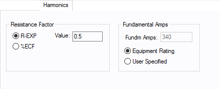
Figure 2: Harmonics Tab
| Option | Description | |||||||||||||||||||||
|---|---|---|---|---|---|---|---|---|---|---|---|---|---|---|---|---|---|---|---|---|---|---|
| Resistance Factor |
EasyPower offers two methods for calculating RH:
RH = RFund * H R-EXP RH = RFund * (1+ECF*H2)/(1+ECF) EasyPower defaults all skin effect correction to R-EXP and a value of 0.5.
|
|||||||||||||||||||||
| Fundamental Amps |
Use to set the fundamental amps. The options are as follows:
To use fundamental current calculated by power flow, select Calculated from Power Flow in the Summation Fundamental Voltage area of the Harmonics Options > Control dialog box. |
Other Tabs
See Common Tabs for information on the Location, Comments, Hyperlinks, or Collected Data tabs.
More Information
| Database Technical Reference | Common Tabs |
| Media Gallery |
|
|