Dynamic Stability Options
Note: If you have purchased only the Transient Motor Starting module and not the Dynamic Stability module, your menus and options will reflect the names "Transient Motor Starting" or "TMS" instead of Dynamic Stability.
Control Tab
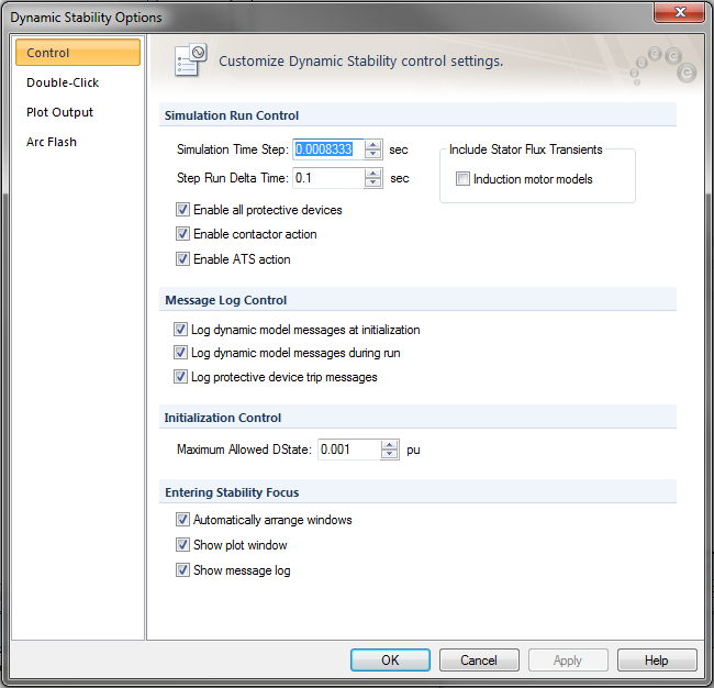
Figure 1: Dynamic Stability Options - Control
| Option | Description |
|---|---|
|
Simulations Run Control |
|
|
Simulation Time Step |
The simulation calculations are performed after every time step (or interval) in seconds. A smaller time step can result in improved accuracy, at the cost of longer simulation completion time. Very large time steps can lead to numerical instability. It is recommended that the time step be smaller than half of the smallest time constant in equipment data. |
|
Step Run Delta Time |
When a simulation is run one step at a time, this is the duration of each run. Step Run is available only with simulation scripts. |
|
Enable all protective devices |
The tripping of protective devices such as relays, circuit breakers, and fuses are enabled during dynamic stability simulations. |
|
Enable contactor action |
Selecting this check box enables contactors to drop out automatically when the voltage drops. |
|
Enable ATS action |
Selecting this check box enables ATS to switch to the alternate source automatically when the primary source is disconnected. |
|
Include Stator Flux Transients |
You can include the effect of transient dc offset in your simulations. Dynamic simulations are normally run in symmetrical rms values. Including the transient dc components in the calculations makes the simulation more realistic. You can include stator flux transient models for the following machine models for induction motors and synchronous motors. |
|
Message Log Control |
|
|
Log dynamic model messages at initialization |
Enabling this option outputs messages in the Message Log regarding the initialization status all equipment with dynamic stability data. |
|
Log dynamic model messages during run |
Enabling this option outputs messages in the Message Log regarding the events that occur during the simulation. |
|
Log protective device trip messages |
When protective devices trip during a simulation, the message log will include the event. |
|
Initialization Control |
|
|
Maximum Allowed DState |
Prior to running a dynamic simulation, the steady state initial condition is determined using this value as the criteria. The DState is the difference between the values of a variable during consecutive steps of computation. When all the DStates settle down to values below the Maximum Allowed DState, the initialization is considered complete. In general, the smaller the value specified for the Maximum Allowed DState, the more accurate is the initialization. However, reducing the value too low can cause failure of initialization or take longer time to settle. |
|
Entering Stability Focus |
|
|
Automatically arrange windows |
When you enter the Dynamic Stability focus, the windows are automatically arranged such that you can view the all of open windows. These windows include the one-line window, and any of the plot and message windows if they are enabled in the Dynamic Stability Options. |
|
Show plot window |
Displays the Dynamic Stability Plot window while entering Dynamic Stability focus. |
|
Show message window |
Displays the Dynamic Stability Message Log window while entering Dynamic Stability focus. |
Double-Click Tab
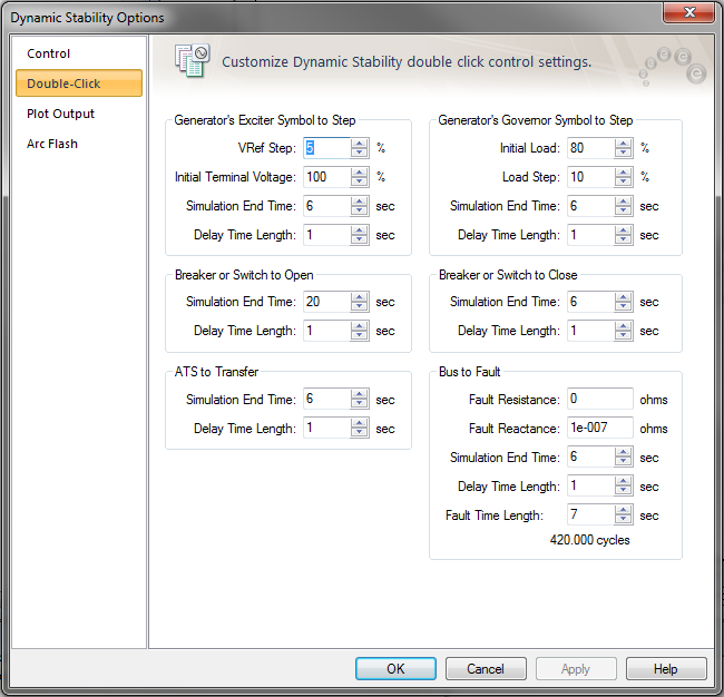
Figure 2: Dynamic Stability Options – Double-Click Tab
| Option | Description |
|---|---|
|
Generator’s Exciter Symbol to Step A step response test on the exciter of a generator lets you to see the effect of increasing the excitation by a specified amount. The AutoPlot tab plots the per-unit generator terminal voltage and the per-unit field voltage. This test treats the generator as isolated from the network. The step test is performed by double-clicking on the generator exciter symbol in the one-line. These options are available only if Dynamic Stability has been purchased. |
|
|
Vref Step |
This is the percent increase in the reference voltage. |
|
Initial Terminal Voltage |
The terminal voltage in percentage of rated voltage before the step is applied. |
|
Simulation End Time |
Simulation is run up to this time. |
|
Delay Time Length |
The step is applied after this delay after the simulation begins. For example, if you specify the delay time length as 1 second, then the step in Vref occurs 1 second after the simulation begins. |
|
Generator’s Governor Symbol to Step A step response test on the governor of a generator enables you to see the effect of increasing the load by a specified amount. The generator speed changes. The AutoPlot tab plots the per-unit generator prime mover power and the per-unit speed. The step test is performed by double-clicking on the generator governor symbol in the one-line. These options are available only if Dynamic Stability has been purchased. |
|
|
Initial Load |
Percent load on the generator at the beginning of the step response test. |
|
Load Step |
Percent increase in the generator load. |
|
Simulation End Time |
Simulation is run up to this time. |
|
Delay Time Length |
The step is applied after this delay after the simulation begins. For example, if you specify the delay time length as 1 second, then the step in the load occurs 1 second after the simulation begins. |
|
Breaker or Switch to Open You can double-click on a breaker or a switch to open or close it. |
|
|
Simulation End Time |
Simulation is run up to this time. |
|
Delay Time Length |
The breaker or switch is opened after the specified delay after the simulation begins. For example, if you specify the delay time length as 1 second, then the breaker or switch opens 1 second after the simulation begins. |
|
Breaker or Switch to Close |
You can double-click on a breaker or a switch to open or close it. |
|
Simulation End Time |
Simulation is run up to this time. |
|
Delay Time Length |
The breaker or switch is closed after the specified delay after the simulation begins. For example, if you specify the delay time length as 1 second, then the breaker or switch closes 1 second after the simulation begins. |
|
ATS to Transfer You can double-click on an ATS to transfer the connection to the alternate source. |
|
|
Simulation End Time |
Simulation is run up to this time. |
|
Delay Time Length |
The ATS connection is transferred to an alternate source after the specified delay after the simulation begins. For example, if you specify the delay time length as 1 second, then the ATS transfers the connection 1 second after the simulation begins. |
|
Bus to Fault You can double-click on a bus to simulate a bus fault (short circuit). |
|
|
Fault Resistance |
Resistance at the fault point in ohms. A bolted fault has the fault resistance of zero. |
|
Fault Reactance |
Resistance at the fault point in ohms. A bolted fault has the fault reactance of zero. |
|
Simulation End Time |
Simulation is run up to this time. |
|
Delay Time Length |
The fault is performed on the bus after the specified delay after the simulation begins. For example, if you specify the delay time length as 1 second, then the fault occurs 1 second after the simulation begins. |
|
Fault Time Length |
The duration for which the fault lasts. If the fault time length is specified as 0.1 seconds, the fault is removed automatically 0.1 seconds after the fault is applied. |
Plot Output Tab
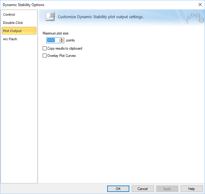
Figure 3: Dynamic Stability Options - Plot Output
| Option | Description |
|---|---|
|
Maximum plot size |
This is the number of data points at various time intervals stored for each variable during a simulation run. |
|
Copy results to clipboard |
When a simulation is run, the data is copied to the clipboard if this check box is selected. You can paste the data to a spreadsheet. |
|
Overlay Plot Curves |
With this check box selected, the plot of various variables overlay each other. If the check box is not selected, the plots are separated and the vertical axes are scaled automatically. |
Arc Flash Tab
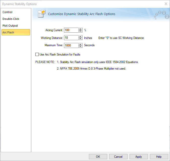
Figure 4: Dynamic Stability Options – Arc Flash
| Option | Description |
|---|---|
| Arcing Current |
You can specify scaling (percentage) for arc current. IEEE Std. 1584-2002 recommends comparing incident energies for 100% arcing current and 85% arcing current. |
| Working Distance |
When the Dynamic Stability Options define the working distance, any user-defined trip times entered in a Bus Data dialog box are ignored. However, if you enter “0” for the Dynamic Stability Working Distance, then the Working Distance defined in the Short Circuit Options are used, including the bus values (when entered). Also, the working distance in Short Circuit Options are always converted to inches for the dynamic stability working distance output. |
|
Maximum Time |
Maximum limit of arc duration. If the trip time is very long, then simulation is carried out up this maximum time. |
|
Use Arc Flash Simulation for Faults |
When this check box is selected, bus faults calculate arc currents and arc flash hazard. All calculations performed are as per the IEEE 1584-2002 standard. When the check box is not selected, bolted fault currents are calculated. |
More Information
| Dynamic Stability | Arc Flash Calculations in Dynamic Stability |
| Short Circuit Options (ANSI) | Creating a Simulation Script |
| Controlling the Analysis |
|
|