ATS Data
This dialog box includes the following areas and tabs:
- Database Dialog Box Toolbar
- Connection Information
- Specifications Tab
- Stability Tab
- Arc Flash Hazard Tab
See Common Tabs for information on the Location, Reliability, Comments, Hyperlinks, Media Gallery, or Collected Data tabs.
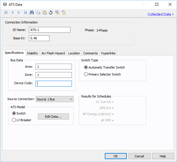
Figure 1: ATS Data Dialog Box
Connection Information
| Option | Description |
|---|---|
| ID Name |
Uniquely identifies the equipment item. The program automatically assigns a name, but you can change it, if needed. The name can be up to 16 characters long. For automatic transfer switches, the program automatically assigns the names ATS-1,ATS-2, ATS-3, and so on. |
| Base kV | Base kV for the ATS. An ATS has three buses as shown by the nodes in the symbol. Note that the bus must have a kV entered before equipment can be connected to the bus. Anything less than 1kV is considered low voltage, anything 1kV or more is high voltage. |
|
Phase |
The phase of the item. Currently, this is for reference only. |
Specifications Tab
Stability Tab
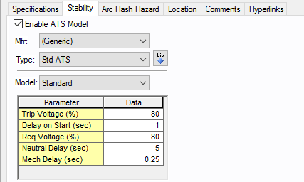
Figure 2: Stability Tab
| Option | Description |
|---|---|
| Enable ATS Model | Select the check box to enter stability information. |
| Manufacturer (Mfr) | Provides a list of manufacturers available in the device library. If the desired manufacturer is not listed in the device library, you can add it to the library. |
| Type | Equipment types available from the selected manufacturer. If the desired type is not listed, you can add it to the library. |
| Model | Equipment models available from the selected equipment type. If the desired model is not listed, you can add it to the library. |
 Lib Lib |
Populates the table with equipment data from the library. See EasyPower Device Library for more information. |
See EasyPower Device Library for more information.
Arc Flash Hazard Tab
EasyPower calculates arc flash risk assessment results using the options set on the Arc Flash Hazard tab. The results are calculated for automatic transfer switches, buses, tool points of connection, MCCs, and panels.
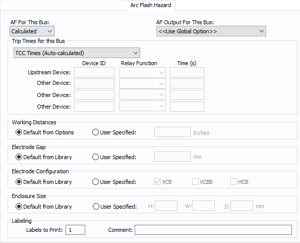
Figure 3: Arc Flash Hazard Tab
| Option | Description |
|---|---|
| AF For This Bus |
You can specify how you would like arc flash results determined for this bus using AF for this Bus. Calculated: When the bus is faulted, EasyPower the performs arc flash hazard analysis using the calculation method specified in Short Circuit Options. EasyPower uses other settings on this tab as part of the calculations. Excluded: Select to exclude the bus from arc flash reports. An example of when you might select this option is for a bus that is required to model the electrical parameters of the system but does not actually represent a piece of electrical equipment. Other applications include nodes and tap-offs (junctions), where energized work is not required. Forced To: When you select this option, you can enter the incident energy and arc flash boundary for this bus. The incident energy and arc flash boundary values are shown on the one-line and in reports and work permits. This can be used for instances where you need to apply a calculation that is outside the scope of the industry standard calculations. |
| AF Output For This Bus |
You can specify whether to display results on the line side or the load side of the Main protective device of the bus equipment. If the arc flash hazards output for this bus needs to be different from the global option, use this field. The choices are:
|
| Trip Times for this Bus |
You can select the method for determining trip times for this bus by choosing from the following:
Note: When a user-defined time is specified and the calculation method is set to use the integrated method, only the upstream device setting is used. The time is considered as the maximum length of the simulation. See The Integrated Method for more information. |
| Working Distances |
You can specify the working distances shown on the one-line and in reports and work permits.
The units displayed are based on the units selected in Arc Flash Hazard Options on the System tab. For inches, the range is 1-1000. For meters, the range is 0.1 to 1000. |
| Electrode Gap |
You can specify the electrode gap shown on the one-line and in reports and work permits.
|
|
Electrode Configuration |
You can specify the electrode configuration shown on the one-line and in reports and work permits.
Electrodes in Enclosures: Electrodes in Open Air: You can select more than one configuration to represent the multiple types of conditions that can occur for the equipment. EasyPower evaluates each configuration and then provides values for the highest incident energy based on the existing electrode configurations. Annex C in the IEEE 1584-2018 standard describes examples where you might use more than one electrode configuration. Tip: To change the electrode configuration for multiple items on the one-line, select the items in the Database Edit focus and then on the Home tab, click Change > AF Bus Electrode Configuration. Electrode configurations are only applicable to the IEEE 1584-2018 standard. For more information, see Electrode Configuration. |
|
Enclosure Size |
You can specify the enclosure size shown on the one-line and in reports and work permits.
The units displayed are based on the units selected in Arc Flash Hazard Options on the System tab. For inches, the range is .01-1000. For millimeters, the range is 0.1 to 25,000. The enclosure dimensions affect arc flash.
|
| Labels to Print |
Enter the number of labels you want to print for arc flash hazard analysis. If you enter "0," no labels will print. |
| Comment |
You can type a comment that appears on the arc flash label when it is printed. For example, you could type a location description for the equipment to assist with label placement. |
Other Tabs
See Common Tabs for information on the Location, Reliability, Comments, Hyperlinks, Media Gallery, or Collected Data tabs.
More Information
| Database Technical Reference | Common Tabs |
| EasyPower Device Library | Electrode Configuration |
| Media Gallery |