Common Tabs
There are several tabs that are common to most or all equipment data dialog boxes. These include:
Location Tab
You can specify the location of the equipment on the floor of a building. You can give the location a name, specify the X and Y coordinates of the location, and select a floor.
The coordinates could be measured in feet, for example, or they could represent points on a grid. There are no units associated with the coordinates, so you can use whatever measurement makes sense for you.
For more information, see Facilities, Floors, and Locations.
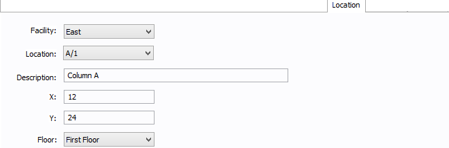
Figure 1: Location Tab
| Option | Description |
|---|---|
|
Facility |
The building in which the equipment is located. Facilities are set up under the Tools > Options arrow under Facilities. |
|
Location |
The location of the equipment. This is the combination of the Ref 1 and Ref 2 boxes set up on the location. Locations are set up under the Tools > Options arrow under Locations. |
|
Description |
This is a description of the location. The default description comes from the location, but you can change it. You can type up to 32 characters. |
|
X |
This is a numeric value (such as feet or grid locations) that represents the horizontal location. The default X value comes from the location, but you can change it. |
|
Y |
This is a numeric value (such as feet or grid locations) that represents the vertical location. The default Y value comes from the location, but you can change it. |
|
Floor |
Select the floor where the equipment is located. Floors are set up under the Tools > Options arrow under Floors. |
Reliability Tab
This tab appears when your EasyPower license includes the optional Reliability feature and the component is included in reliability analysis. Use this tab to track reliability data on your system components. The reliability features are based on IEEE Standard 493-2007. Refer to the standard for additional information.
For lines such as cables, busways, and transmission lines, also see Reliability Data for Cables, Busways, and Transmission Lines.
Note: Rectifiers, inverters, and AFDs are treated as single nodes (branches) and their reliability data applies directly to them. These can become dependent first-order cut sets if connected to first-order buses.
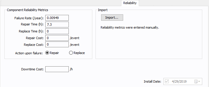
Figure 2: Reliability Tab
| Option | Description |
|---|---|
|
Import |
Click Import to import reliability data from the selected library, class, and category into the reliability data fields. After you import, the imported values appear below the Import button.
Note: You can also import reliability data for all components in the one-line at the same time. |
|
Failure Rate |
The calculated rate of failure for the component on a yearly basis. If you have imported library data, the imported value is displayed here. You can manually type a value to have the program use that value instead. Note: For cables, transmission lines, and busway, this value is per unit of length. |
|
Repair Time |
The mean average time to repair the component, expressed in hours. If you have imported library data, the imported value is displayed here. You can manually type a value to have the program use that value instead. Note: For cables, transmission lines, and busway, this value is per unit of length. |
|
Replace Time |
The mean average time to replace the component, expressed in hours. If you have imported library data, the imported value is displayed here. You can manually type a value to have the program use that value instead. Note: For cables, transmission lines, and busway, this value is per unit of length. |
|
Repair Cost |
The estimated cost to repair the component. This value is not used if the Action upon failure is set to Replace. |
|
Replace Cost |
The estimated cost to replace the component. This value is not used if the Action upon failure is set to Repair. |
|
Action upon failure |
The recommended action to take upon failure of the component: repair, or replace. |
|
Downtime Costs |
The downtime cost for the individual piece of equipment. This is available for a bus, MCC, panel, motor, or load. |
|
SC Failure Mode (%) |
This is an adjustable percentage that is applied to the failure rate of indirect protective devices and represents the percentage of total failures in each failure mode. For circuit breakers, the default is 9%. For switches, the default is 0% (no reliability). |
|
Install Date |
This option is reserved for future use. |
Reliability Data for Cables, Busways, and Transmission Lines
Lines such as cables, busways, and transmission lines have some additional fields that relate to their connections. Each line has two connections: one on the line side and one on the load side. The connection reliability metrics are per connection.
If the unit is specified as Per Unit on the Specifications 1 tab, the per unit length that the reliability is based on appears here.
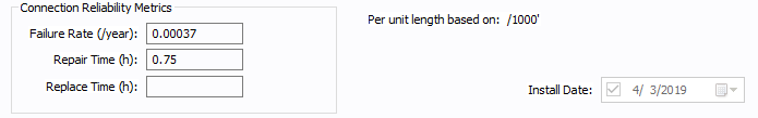
Figure 3: Cable Connection Reliability Data
Comments Tab
All equipment data dialog boxes contain a Comments tab. Use this space to write notes on the device.
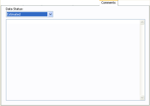
Figure 4: Comments Tab in Equipment Data Dialog
| Option | Description |
|---|---|
| Data Status | Enables you to specify whether the data entered for this item is estimated, verified or incomplete. You can run a query to select items that are incomplete or estimated. Then you can color code the selected items by picking a color from the color palette. |
| (Comment Area) | Type the comments you want to attach to this equipment item. |
Hyperlinks Tab
Use hyperlinks to link to additional documentation or URLs outside the device library.

Figure 5: Hyperlink Tab of Equipment Data Dialog Box
Every equipment data dialog has a Hyperlink tab. Use it to create links to additional reference information. This can be documentation or web URLs, for example.
Tip: It isn't required that you link to individual documents. For example, if you have all your equipment documentation stored in a particular folder on your network, you can copy and paste the folder path into the File or Web Page Name box. Anyone who has access to the folder will be able to click the link to open the folder location and view the documentation related to the selected equipment.
You can also hyperlink work permits created by EasyPower.
Note: Your computer must have the related program installed to open the file—for example, to open an Excel spreadsheet, you must have a program that opens Excel files installed.
| Option | Description |
|---|---|
|
Open |
Opens the selected hyperlink. You can also double-click on a hyperlink to open it. |
|
Delete |
Deletes the selected hyperlink. |
|
Add |
Click to open the Add Hyperlink dialog box. Type the text you want to appear in Text to Display box and select the file to which you want to link by clicking Browse. You can also type the URL of a web page. Click Open Link to view the linked item or web page and verify that the link works. |
|
Edit |
Click to open the Edit Hyperlink dialog box. Type the text you want to appear in Text to Display box and select the file to which you want to link by clicking Browse. You can also type the URL of a web page. Click Open Link to view the linked item or web page and verify that the link works. |
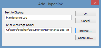
Figure 6: Add Hyperlink Dialog Box
To open the file or URL in the list, double-click the item or select it and click Open. You can also delete or edit the hyperlink.
Media Gallery Tab
Use this tab to store media such as pictures of the equipment. You can add media from a file on your computer or you can link to media that is already in the Media Gallery. If you import media, such as from an OnSite project, the media appears here.
You can toggle between having the tab hidden or displayed by clicking the blue arrow in the corner of the data dialog box, as shown below.
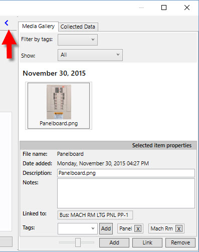
Figure 7: Media Gallery Tab in Data Dialog Box
| Option | Description |
|---|---|
| After you create tags for a media file (see Tags), you can filter by the tag name by selecting the tags here. You can filter by multiple tags. | |
| Show | Enables you to further filter the images shown, such as by an OnSite data import. |
| (Media area) |
Thumbnails of the media files are displayed here, arranged by date. You can use the slider at the bottom of the dialog box to increase or reduce the size of the thumbnails. The name that appears on the file comes from the Description field. Click on a thumbnail to open the file. |
| File name | The name of the media file. It is for reference only. |
| Date added | The date the file was added—for example, when it was imported. |
| Description | The description of the file. If you change the name here, it changes the name on the thumbnail, but does not change the name of the file itself. This option is not available if more than one media file is selected. |
| Notes | Notes for the selected media file. This option is not available if more than one media file is selected. |
| Linked to | The equipment to which the media file is linked. There can be more than one. |
| Tags | You can add a tag to a media file by selecting the file, typing the tag name (or selecting an existing tag), and then clicking Add. The name appears to the right. You can add multiple tags to a media file. Tags are useful for filtering media files. See Filter by tags. |
| Add |
Add a media file to the equipment item, such as a file that is somewhere on your computer. This is slightly different from Link, which lets you link to a media file that is already in the Media Gallery. |
| Link |
Link an existing media file in the Media Gallery to the equipment. This is slightly different from Add, which lets you add media to the Media Gallery from your computer. |
| Remove | Remove the selected media file or files from the equipment. |
See also Media Gallery.
Collected Data Tab
This tab appears only if you have imported data. It is listed for reference only.
You can toggle between having the tab hidden or displayed by clicking the blue arrow in the corner of the data dialog box, shown below.
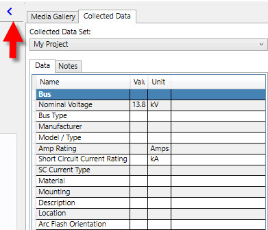
Figure 8: Connected Data Tab
| Option | Description |
|---|---|
|
Collected Data Set |
The source of the data, such as an import from SKM, OnSite or Revit. |
|
Data |
The data that was imported. It is for reference only, and cannot be changed. |
See Importing an SKM Format File, Importing an OnSite Data File, and Importing from Revit to EasyPower for more information.