Current Limiting (C.L.) Reactor Data
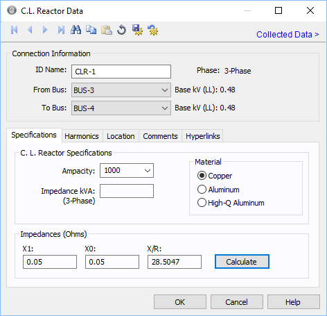
This dialog box includes the following areas and tabs:
See Common Tabs for information on the Location, Reliability, Comments, Hyperlinks, Media Gallery, or Collected Data tabs.

Figure 1: Current Limiting Reactor Data Dialog Box
Connection Information
Specifications Tab
| Option | Description |
|---|---|
| Ampacity |
This field provides a list of industry standard reactor ampere ratings, but you can also type in a rating which is not listed. |
| Impedance kVA |
3-phase reactor impedance kVA. This value is used to determine the impedance and X/R ratio of the reactor. If this value is not known, you must enter the positive and zero sequence impedance (X1 and X0) to compute the X/R ratio with the Calculate button. The Impedance kVA is calculated with the following equation: Impedance kVA3ph = 3(IL)2(Xohm)/1000 |
| Material |
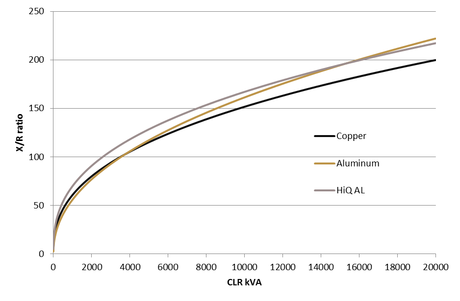
Reactor material (copper, aluminum, or high-Q aluminum). This value is used to determine the X/R ratio of the reactor.
Figure 2: CLR X/R Ratio w.r.t. Device Rating |
| Impedances | |
| X1 | Positive sequence impedance. When filled in with the Calculate button, this field’s value is based on the reactor impedance kVA. |
| X0 | Zero sequence impedance. When filled in with the Calculate button, this field’s value is considered the same as the positive sequence impedance X1. If you enter this value as zero (0.0), the positive sequence impedance is used. |
| X/R Ratio | The reactance to resistance ratio of the reactor. When filled in with the Calculate button, this field’s value is based on the impedance kVA and the material type of the reactor. |
| Calculate | Fills in computed values for the X1, X0, and X/R fields. You can override these values by typing in different numbers. |
Harmonics Tab
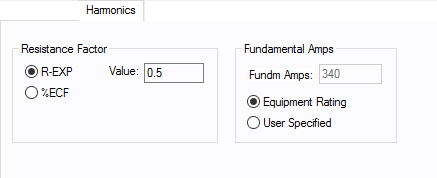
Use the Harmonics tab to indicate whether this equipment item is introducing harmonics into your power system.
Figure 3: Harmonics Tab
| Option | Description | |||||||||||||||||||||
|---|---|---|---|---|---|---|---|---|---|---|---|---|---|---|---|---|---|---|---|---|---|---|
| Resistance Factor |
EasyPower offers two methods for calculating RH:
RH = RFund * H R-EXP RH = RFund * (1+ECF*H2)/(1+ECF) EasyPower defaults all skin effect correction to R-EXP and a value of 0.5.
|
|||||||||||||||||||||
| Fundamental Amps |
Use to set the fundamental amps. The options are as follows:
To use fundamental current calculated by power flow, select Calculated from Power Flow in the Summation Fundamental Voltage area of the Harmonics Options > Control dialog box. |
Other Tabs
See Common Tabs for information on the Location, Reliability, Comments, Hyperlinks, Media Gallery, or Collected Data tabs.
More Information
| Database Technical Reference | Common Tabs |
| Media Gallery |


