Fused Switch Data

This dialog box includes the following areas and tabs:

See Common Tabs for information on the Location, Reliability, Comments, Hyperlinks, Media Gallery, or Collected Data tabs.

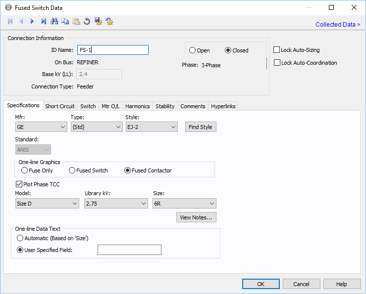
Figure 1: Fused Switch Data Dialog Box

Connection Information

Option Description
ID Name

Uniquely identifies the equipment item. The program automatically assigns a name, but you can change it, if needed. The name can be up to 16 characters long.

For fused switches, the program automatically assigns the names FS-1, FS-2, FS-3, and so on.

Open

Normal state of the fused switch. If selected, the one-line displays “OPEN” next to the fused switch symbol.

Closed If selected, the one-line does not display “OPEN” next to the fused switch symbol.
On Bus The bus connected to the fuse switch, which must already exist on the one-line.
Base kV

The kV of the bus to which the fuse switch is connected. The options available in the Specifications tab and Short Circuit tab depend on the bus voltage. Either LV or HV fused switches can be selected from this dialog box. Although the EasyPower Device Library has HV and LV Fused Switches as separate devices, the same dialog box is used to select both types.

Connection Type Whether the fused switch is connected as a “Feeder,” (to a cable, busway, or transformer, for example.) or as a “Tie” (between two buses).

Phase

The phase of the item. Currently, this is for reference only.

Group Name/Type If the fused switch is part of a functional group, the group name and type appears here. See Functional Groups.
Lock Auto-Sizing

When this check box is selected, this item cannot be automatically sized using SmartDesign™ (the auto-design feature).

Lock Auto-Coordination

When this check box selected, this item cannot be automatically sized using SmartPDC™ (the auto-coordination feature).

Specifications Tab

Option Description
Mfr Provides a list of manufacturers available in the device library. If the desired manufacturer is not listed in the device library, you can add it to the library.
Type Equipment types available from the selected manufacturer. If the desired type is not listed, you can add it to the library.
Style Equipment models available from the selected equipment type. If the desired model is not listed, you can add it to the library.
Find Style Enables you to search the library for a fuse style.

Standard

Displays the standard used for short circuit calculation based on the selected type.

One-line Graphics

Select the symbol that appears on the one-line diagram.

  • Fused Switch: Default setting that will show a fused switch symbol on the one-line diagram.
  • Fused Contactor: A fused contactor symbol will show on the one-line diagram.
  • Fuse Only: Shows fuse only in the fuse symbol (without either contactor or switch).
Plot Phase TCC Select this check box to plot the TCC for the fused switch. If the check box is not selected, the TCC for the device is not plotted.
Model This field enables you to view available models of the fuse style that you have chosen and to select a specific model.
Library kV Choose the section of the library the fuse data is entered. In most cases, the selected Library kV is approximately the base kV of the fuse. For LV fuses, this field is blank.
Size This field enables you to view available sizes of the fuse model that you have selected and select a specific size.
View Notes Click to view notes recorded in the library for the device. Information may include data sheets or manufacturer's information for the device or assumptions needed to model the device.
One-line Data Text

Use to select text to appear on one-line diagram. For text to appear next to symbols on the one-line diagram, choose Tools > Options > Text Visibility and select the check box for Fused Switch.

  • Automatic (Based on ‘Size”): When selected, fuse size appears next to the fused switch on the one-line diagram.
  • User Specified Field: When selected, you can enter text information that appears on the one-line.

Short Circuit Tab

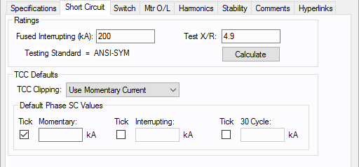
Figure 2: Fused Switch Short Circuit Dialog Box (ANSI)

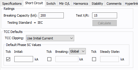
Figure 3: Fused Switch Short Circuit Dialog Box (IEC)

Option Description
Ratings
Fused Interrupting (kA) The interrupting rating of the fused switch (ANSI).

Breaking Capacity (kA)

The breaking capacity of the fused switch (IEC).

Test X/R Test X/R ratio of the circuit. ANSI Standard test ratios might be different for the same fuse depending on the voltage level at which the fuse is applied.
Testing Standard This comes directly from the device library and cannot be changed.
Calculate Fills in computed values for the Test X/R and Fused Interrupting fields, based on the device library entry for Mfr, Type, Style, and the base kV. You can override these values by typing in different numbers. This button also causes the appropriate Testing Standard to be displayed for your information.

TCC Defaults

Data entered in this section is used to place tick marks representing short circuit values on the TCC plot.

TCC Clipping

You can clip the time current curve (TCC) for the breaker at the specified current in kA. Select <None> to avoid clipping of TCC.

  • For ANSI, select Momentary (1/2 cycle), 5-cycle or 30-cycle.
  • For IEC, select Initial, Breaking, or Steady State.
SC Tick Marks

Select the appropriate check boxes to display the tick mark on the TCC plot.

  • For ANSI, you can display Momentary, Interrupting and 30 Cycle short circuit values. Enter the corresponding short circuit values in kilo amps in their respective edit fields for phase short circuit.
  • For IEC, Select Initial, Breaking, or Steady State. If you select Breaking, you can select the breaking values. The options are Global, 0.02, 0.05, 0.1, or > 0.25. Global is derived from the Short Circuit Options on the Control tab.
Default Phase SC Values The short circuit values entered in kA in these fields can be displayed for phase currents on TCC plots.

Switch Tab

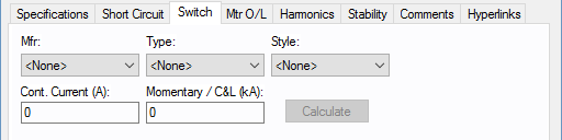
Figure 4: Switch Tab

Option Description
Mfr Provides a list of manufacturers available in the device library. If the desired manufacturer is not listed in the device library, you can add it to the library.
Type Equipment types available from the selected manufacturer. If the desired type is not listed, you can add it to the library.
Style Equipment models available from the selected equipment type. If the desired model is not listed, you can add it to the library.
Cont. Current (A) Continuous current rating of the switch.

Momentary / C&L (kA)

Peak Withstand (kA)

The momentary or close and latch rating of the switch (ANSI).

The peak withstand for the switch (IEC).

Calculate Fills in device ratings based on library entries for the specified switch.

Mtr O/L (Motor Overload) Tab

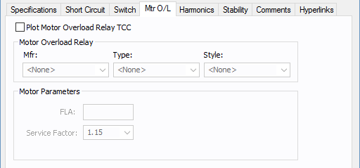
Figure 5: Fused Switch Mtr O/L Dialog Box

Option Description
Plot Motor Overload Relay TCC To plot the TCC of an attached motor overload relay with the fused switch TCC, select this check box. If you do not select this check box, then no TCC is plotted for an attached motor overload relay.
Motor Overload Relay

Specify the motor overload relay associated with the breaker in protecting the motor.

  • Mfr: Provides a list of motor overload relay manufacturers available in the device library. If the desired manufacturer is not listed, you can add it to the library.
  • Type: Provides a list of motor overload relay types available from the manufacturer chosen above. A type would include a group of models or brands with similar functions. Equipment types available from the selected manufacturer. If the desired type is not listed, you can add it to the library.
  • Style: Provides a list of motor overload relay styles available from the type chosen above. Styles are essentially models. If the desired style is not listed, you can add it to the library.
Motor Parameters

Determines the pickup level for the motor overload relay.

Full Load Amps (FLA): The full load amps specified for the motor, or the relay rating.

Service Factor: Overload factor of the rated amps. This factor does not increase the rating but simply increases the pickup level. You may enter any value between 1.0 and 1.25.

Harmonics Tab

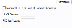
Figure 6: Harmonics Tab

Option Description
Monitor IEEE 519 Point of Common Coupling

EasyPower can monitor whether or not the IEEE 519 guideline for harmonics is met at the point of common coupling.

If selected, then the Harmonics Report indicates when this guideline is not being met.

kVA Demand The kVA demand.
PCC Isc/Load The ratio of short circuit current to load current at the point of common coupling.

Stability Tab

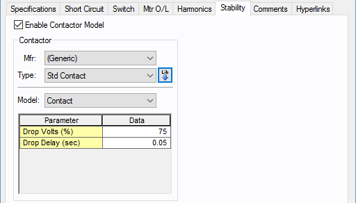
Figure 7: Fused Switch - Stability Tab

Option Description
Enable Contactor Model Select the check box to enter stability information.
Mfr Provides a list of manufacturers available in the device library. If the desired manufacturer is not listed in the device library, you can add it to the library.
Type Equipment types available from the selected manufacturer. If the desired type is not listed, you can add it to the library.
Model Equipment models available from the selected equipment type. If the desired model is not listed, you can add it to the library.
Lib Populates the table with equipment data from the library. See EasyPower Device Library for more information.

Other Tabs

See Common Tabs for information on the Location, Reliability, Comments, Hyperlinks, Media Gallery, or Collected Data tabs.

More Information

Database Technical Reference Common Tabs
Media Gallery