Switch Data
This dialog box includes the following areas and tabs:
- Database Dialog Box Toolbar
- Connection Information
- Specifications Tab
- Short Circuit Tab
- Harmonics Tab
See Common Tabs for information on the Location, Reliability, Comments, Hyperlinks, Media Gallery, or Collected Data tabs.
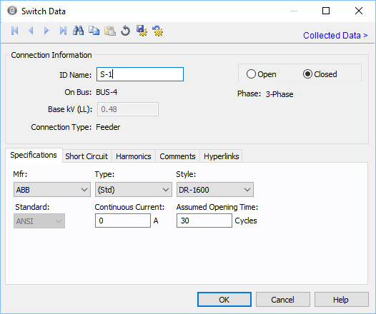
Figure 1: Switch Data Dialog Box
Connection Information
| Option | Description |
|---|---|
| ID Name |
Uniquely identifies the equipment item. The program automatically assigns a name, but you can change it, if needed. The name can be up to 16 characters long. For switches, the program automatically assigns the names SW-1, SW-2, SW-3, and so on. |
| On Bus |
This is the ID name of the bus to which the equipment is connected. The base kV of the bus is indicated on the right. |
| Connection Type |
Whether the switch is connected as a Feeder (such as to a cable, busway, or transformer) or as a Tie (between two buses). |
| Open/Closed | Normal state of the switch. If Open, the one-line displays "OPEN" next to the switch symbol. If Closed, the one-line symbol does not show the "OPEN" tag. |
|
Phase |
The phase of the item. Currently, this is for reference only.
|
| Group Name/Type | If the switch is part of a functional group, the group name and type appears here. See Functional Groups. |
Specifications Tab
| Option | Description |
|---|---|
| Mfr |
Provides a list of manufacturers available in the device library. If the desired manufacturer is not listed in the device library, you can add it to the library. If the desired manufacturer is missing from the list, select Other. |
| Type |
Equipment types available from the selected manufacturer. If the desired type is not listed, you can add it to the library. If the desired manufacturer is missing from the list, select Other. |
| Style | Switch styles available from the manufacturer chosen in the Mfr field above in the type specified. After you choose a manufacturer and type, the styles available in the yellow column of the corresponding device library page are displayed here. |
|
Standard |
Displays the standard used for short circuit calculation based on the selected type of fuse. |
| Continuous Current | Continuous current of the switch. This value is for reference only and does not affect analysis. |
|
Assumed Opening Time |
The estimated time it takes to open the circuit. |
Short Circuit Tab
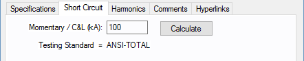
Figure 2: Short Circuit tab of Switch Data Dialog Box (ANSI)
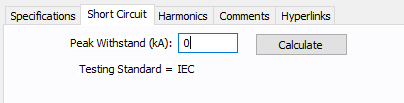
Figure 3: Short Circuit tab of Switch Data Dialog Box (IEC)
Harmonics Tab
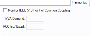
Figure 4: Harmonics Tab
Other Tabs
See Common Tabs for information on the Location, Reliability, Comments, Hyperlinks, Media Gallery, or Collected Data tabs.
More Information
| Database Technical Reference | Common Tabs |
| Media Gallery |