Arc Flash Hazard Reports
Arc flash hazard reports are generated in the form of a spreadsheet. To generate the report:
- Ensure the Arc Flash Spreadsheet check box is selected under Short Circuit Options > Arc Flash Hazard.
- Fault one or more buses in the Short Circuit focus.
- Click
 Arrange for Arc Flash or press F8 to view the report. You can also select
Arc Flash Hazard Report under the
Window button to display the report.
Arrange for Arc Flash or press F8 to view the report. You can also select
Arc Flash Hazard Report under the
Window button to display the report.
The following figure shows a report for faulting “SWG-4” in a sample one-line. This report shows the arc flash results for only the protective device upstream to the bus. When Bus Hazards (Incl Main) is selected in Short Circuit Options - Arc Flash Hazard, only the significant upstream protective devices are reported.

Figure 1: Arc Flash Hazard Report Spreadsheet for Bus Hazards (Incl Main) Option
Interactive Blue Text
The arc flash hazard report is an interactive spreadsheet. Notice there are cells with blue text under the columns Electrode Gap, Bolted Fault (kA) and Arc Time (sec). You can change these numbers to see the effect on the incident energies and arc flash boundaries. The results on the spreadsheet will change automatically. This feature enables you to test for different possible scenarios so that the most conservative estimates can be obtained.
Incident energy is reported for every working distance specified in Short Circuit Options. You can specify up to five different working distances. This is particularly suitable when hot sticks are used to operate devices from some distance. When you first open the Arc Flash Hazard Report window, only the first working distance appears in the spreadsheet.
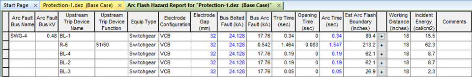
Figure 2: Arc Flash Hazard Report Spreadsheet for Detailed Option
Multiple Working Distances
To view results for other working distances, click  to the left of the Working Distance column in the spreadsheet.
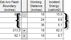
Figure 3: Working Distances Expanded
Pink Text in the Spreadsheet
The spreadsheet displays pink text in certain conditions, depending on the standard selected.
- If the standard specified in Short Circuit Options is IEEE 1584-2018, then when the arc flash results are derived from the reduced arcing current calculated in the IEEE 1584-2018 equations, the text is displayed in pink.
- If the standard specified in Short Circuit Options is anything other than IEEE 1584-2018, then when 85% of calculated arc current (or the lower value specified as worst-case arcing current) yields a greater arc flash incident energy, the text results are displayed in pink.
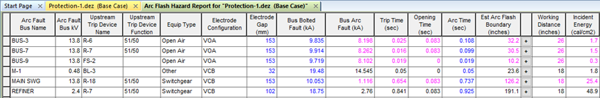
Figure 4: Pink Text for Reduced Arcing Current
In the printed Arc Flash Hazard report, the results for those devices for which arc current matches either of these conditions are marked with an asterisk (*).
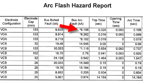
Figure 5: Asterisks on the Arc Flash Hazard Report
Arrange for Arc Flash
At times, it may be required to view both the one-line results and the spreadsheet (see example below). This helps to analyze more closely. To open this view, press F8, or with the one-line window selected, click Arrange for Arc Flash.
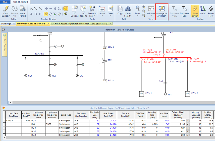
Figure 6: Viewing Report and One-line Results
Spreadsheet Column Headings
The report displays the columns based on the report configuration you have selected. The default configuration displays the columns that are relevant for arc flash, but you can choose to include additional columns. The default columns change slightly depending on which arc flash hazard standard you have selected. See Customizing the Arc Flash Hazard Report for more information.
| Option | Default? | Description |
|---|---|---|
|
Arc Fault Bus Name |
Yes |
This is the ID name of the buses faulted. You can have single or multiple (including all buses) faulted for arc flash analysis. MCC and panel schedules also are presented as buses; this represents the main bus within the MCC or panel. |
|
Bus Area |
|
The area of the electrical system in which the bus is located. This can be used to analyze the system in sections. |
|
Bus Zone |
|
The zone in the area of the electrical system in which the bus is located. This can be used to analyze the system in sections. |
|
Arc Fault Bus kV |
Yes |
The voltage of the bus being faulted. |
|
Location Description |
|
The name of the physical location where the equipment is located. |
|
Location X |
|
The X coordinate of the equipment location |
|
Location Y |
|
The Y coordinate of the equipment location. |
|
Floor |
|
The floor on which the equipment is located. |
|
AC/DC |
|
Indicates whether the equipment uses alternating current or direct current. |
|
L-G Bus kV |
|
The line-to-ground voltage of the bus being faulted. |
|
Device Code |
|
The QR (Quick Response) code for the device, which is available to print on arc flash labels. |
|
Upstream Trip Device Name |
Yes |
When a bus is faulted, EasyPower checks every protective device for the current contribution to the fault. If the current passing through the protective device is significant, then the results corresponding to the trip time of that device are provided in the spreadsheet. |
|
Upstream Bus Name |
|
The name of the bus to which the reported upstream device is connected. |
|
Upstream Function ID |
|
If the trip device is a relay, then the relay function ID is provided in this column. |
|
Upstream Trip Device Function |
Yes |
If the trip device is a relay, then the device function name is provided in this column. Examples of device functions are: 51/50, 51N, 50G, 49, and so on. |
|
Equipment Type |
Yes |
Describes the type of enclosure specified in the Bus Data. The available types are Switchgear, MCC/Panel, Open Air and Conductor. |
|
Gnd |
Yes* |
The “X” mark in this column indicates if the IEEE equation used the coefficient for solidly grounded systems. This only applies if the standard selected is something other than IEEE 1584-2018. The zero sequence impedances for cables and busways are typically higher than the positive sequence impedances. Therefore, the line to ground fault currents can be smaller than three phase faults at the end of a long line. When the line to ground fault current is much smaller than the three phase fault current then the system can be considered “not effectively grounded." To determine if the system is effectively grounded, the program first performs a single line to ground fault on A phase. The average per-unit voltage at B and C phases is compared with the threshold specified in the Arc Flash Gnd Vpu field in the Options - System dialog box. If the average per-unit voltage is less than the threshold, the system is considered to be effectively grounded. |
|
Electrode Configuration |
Yes |
The electrode configuration on which the arc flash calculations are based. This takes into account whether the conductors are in an enclosure or in open air, as well as the orientation of the conductors and whether they terminate into an insulated barrier. This comes from the device library or it can be specified by the user in the equipment data. Electrode configurations are only applicable to the IEEE 1584-2018 standard. See Electrode Configuration for more information. |
|
Height |
Yes |
The height of the enclosure, based on the electrode configuration. This comes from the device library or it can be specified by the user in the equipment data.This is applicable only when the IEEE 1584-2018 standard is used, and is otherwise left blank. The units displayed are dependent on the Units setting in Tools > Options > System. |
|
Width |
Yes |
The width of the enclosure, based on the electrode configuration. This comes from the device library or it can be specified by the user in the equipment data. This is applicable only when the IEEE 1584-2018 standard is used, and is otherwise left blank. The units displayed are dependent on the Units setting in Tools > Options > System. |
|
Depth |
Yes |
The depth of the enclosure, based on the electrode configuration. This comes from the device library or it can be specified by the user in the equipment data. This is applicable only when the IEEE 1584-2018 standard is used, and is otherwise left blank. The units displayed are dependent on the Units setting in Tools > Options > System. |
|
Electrode Gap |
Yes |
Gap between the phase conductors. This comes from the device library or it can be specified by the user in the equipment data. The gap can be specified according to enclosure type and voltage. It is always expressed in millimeters. The text in this column is blue indicating you can change the values. If you change the value, other calculations in the spreadsheet are automatically updated based on the revised value. |
|
Bus Bolted Fault (kA) |
Yes |
This is the total bolted fault current calculated at the faulted bus. The text in this column is blue indicating you can change the values. If you change the value, other calculations in the spreadsheet are automatically updated based on the revised value. |
|
Bus Arc Fault (kA) |
Yes |
This is the total arcing current calculated at the faulted bus. |
|
Branch Bolted Fault (kA) |
|
The bolted fault current flowing through the upstream protective device. When there are multiple sources or motors feeding the fault, this value can be different from the total bolted fault current on the bus. Also, when the trip device is at different voltage than the bus, the values can be different. The text in this column is blue indicating you can change the values. If you change the value, other calculations in the spreadsheet are automatically updated based on the revised value. |
|
Branch Arc Fault (kA) |
|
The arcing current flowing through the upstream protective device. When there are multiple sources or motors feeding the fault, this value can be different from the total arc current on the bus. Also, when the trip device is at different voltage than the bus, the values can be different. |
|
Trip Time (sec) |
|
Trip time for the protective device at the estimated arc current. |
|
Trip Time (branch bolted fault) (sec) |
Yes |
This column reports the upstream device trip time based on the momentary (1/2 cycle) branch current. This is in compliance with NEC (NFPA 70) 2017 version Article 110.16 (B). |
|
Opening Time (sec) |
Yes |
Opening time for HV breakers or opening device after the relay trips. This column is applicable only for relays. After the relay trips, the HV breaker takes this amount of time to clear the fault. If the trip device is a fuse or LV breaker instead of a relay, the trip time already includes the opening time so this column will be blank. There are some exceptions that apply to this. Some relays already include the breaker opening time in their trip curves. These are referred to as SST Relays. Examples are: Cutler-Hammer Digitrip 1150V, Digitrip MCV, and so on. In the Relay Data dialog, you can specify which breaker, fuse or switch is opened when the relay trips. The opening time from the dialog of the switching device is used. If the ID name of the switching device is not specified, the opening time of the breaker right next to the relay is used. If there are no immediate switching devices, the program will traverse upstream to find the first switching device. |
|
Arc Time (sec) |
Yes |
Total duration of arc fault. This is the sum of Trip Time and Opening Time. If an Aux Time is specified in the relay dialog, the Arc Time includes Aux Time, Trip Time, and Opening Time. The text in this column is blue indicating you can change the values. If you change the value, other calculations in the spreadsheet are automatically updated based on the revised value. |
|
Clearing Time (branch bolted fault) |
No |
The sum of the Trip Time (branch bolted fault) and the Opening Time. |
| Estimated Arc Flash Boundary |
Yes |
The arc flash boundary distance in specified units. Units are specified in Short Circuit Options on the Arc Flash Hazards tab. |
|
Limited Approach Boundary |
|
Shock protection boundary based on equipment voltage according to NFPA 70E. Unqualified persons are not permitted to approach nearer than this distance. |
|
Restricted Approach Boundary |
|
Shock protection boundary based on equipment voltage according to NFPA 70E. When equipment is energized, qualified persons are not permitted to approach or take any conductor or circuit parts closer than the restricted approach boundary. Refer to NFPA 70E for exceptions. |
|
|
|
When you first open the Arc Flash Hazard Report window, only the first working distance appears in the spreadsheet. To view results for other working distances, click |
|
Working Distance |
Yes |
Approximate working distance in specified units. You can specify up to five different working distances in Short Circuit Options. The program calculates incident energy for each working distance. |
|
Incident Energy |
Yes |
This is the incident energy from arc flash corresponding to the trip device. The trip time associated with the trip device is used in the calculation. However, the arc current or fault current used is the total fault current on the faulted bus and not the current seen by the trip device. The rating of personal protective equipment (PPE) worn by workers should be based on this value. The energy is reported in calories or joules per square centimeter based on settings in Short Circuit Options. |
|
PPE Level |
|
This displays the PPE level text based on the levels and text defined in the PPE Levels section of the device library. |
|
PPE Description |
|
This displays the PPE clothing description based on the levels and description defined in the PPE Levels section of the device library. |
|
Comments/ PPE Level |
Yes* |
Comments generated by EasyPower–for example, "No Valid Trip Device Found Upstream or in Bus Dialog." or "Do not Work on Energized Equipment." If EasyPower is set to display the PPE level, this column is named PPE Level and it displays the PPE level. Note: This dual-purpose column was retained for backwards compatibility with earlier custom report configurations, but has been replaced with the separate PPE Level and Equipment Comments columns. It is no longer part of the default report configuration. |
|
Equipment Comments |
|
Comments generated by EasyPower–for example, "No Valid Trip Device Found Upstream or in Bus Dialog," "Do not Work on Energized Equipment," or "Out of IEEE 1584-2018 Range." See IEEE 1584-2018 Range of Model for more information on that message. |
|
Equipment Label Comment |
|
The arc flash label comment. This is defined on the Arc Flash Hazard tab of the equipment dialog box, but can be changed here, if needed. |
|
Equipment Label Quantity |
|
The number of arc flash labels to print. This is defined on the Arc Flash Hazard tab of the equipment dialog box, but can be changed here, if needed. Note: See also Device Label Quantity below. |
|
Device Label Comment |
|
When the Detailed output option is selected, feeder arc flash results are displayed along with bus and incomer results. Each row of the result can have its own user-specified comments. These comments are associated with the protective devices. The comments can be entered only through the arc flash hazard report. The comments are stored with the file. Note: The Detailed output option is set in Short Circuit Options > Arc Flash Hazard. |
|
Device Label Quantity |
|
This is the number of labels to print for each row that is created when the output option is set to Detailed. For this count to be used, the Equipment Label Quantity value must be 0. Note: The Detailed output option is set in Short Circuit Options > Arc Flash Hazard. |
|
*For calculation methods other than IEEE 1584-2018. |
||
Opening the Arc Flash Hazard Report in Excel®
You can open the Arc Flash Hazard report in Excel®. To do so, click the report to display the Table Report tab, and then click  Open With Excel. You can also right-click on the spreadsheet and click Open in Excel.
Customizing the Arc Flash Hazard Report
You can create a customized report layout. To customize the report:
- Ensure the Arc Flash Hazard report is selected, and then click
 Report Config.
 - In the Database Print Config dialog box, select the columns you want to appear on the report.
- Click Save Configuration.
- In the Save Configuration window, in Configuration name, type the name of the configuration file, and then click Save.
See also Sharing Report Configurations.
Deleting Rows from the Report
You can delete individual or multiple rows from the report. When deleting multiple rows, the rows must be contiguous (one right after the other).
Highlight the rows you want to delete, and then press the DELETE key.
If you want to restore the deleted rows, run the report again.
More Information
| Arc Flash Hazard Analysis | IEEE 1584-2018 Range of Model |
| Table Report Tab |