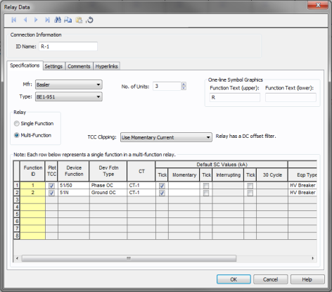
This dialog box includes the following areas and tabs:

Figure 1: Relay Data Dialog Box
ID Name: Uniquely identifies the Relay. This ID name is sometimes referred to as the Relay name, and can be up to 12 characters long. The names default to R-1, R-2, R-3, and so on as you enter new relays on the one-line diagram, but you can change those names if needed.
Mfr: Provides a list of relay manufacturers available in the device library. After you choose a manufacturer, the available types are displayed in the Type field. If the desired manufacturer is missing from the list, you can enter the data in the EasyPower library.
Type: Provides a list of relay types available from the manufacturer chosen above. A type is essentially a model name.
No. of Units: Number of relay units of the same type that are part of a relay system.
One-line Symbol Graphics: You can make the desired text appear inside the relay symbol by typing in Function Text (upper) and Function Text (lower). You can type up to 4 characters each. EasyPower assigns the text “R” in the upper field by default.
Motor/Equipment Parameters: These are parameters of the equipment being protected by the relay. For example, a motor relay would require the full load current as a parameter.

Figure 2: Motor/Equipment Parameters
Generator Parameters: Full load amps (FLA) of the generator is entered here. This section appears in the dialog box only for those relays which have been entered in the library as generator protection relays. EasyPower calculates pickup amps from FLA and pickup setting

Figure 3: Generator Parameters for Generator Relays
Relay: Number of trip units or relay functions set differently. You can select either Single Function or Multi-Function. One device function can have a time-overcurrent function and an instantaneous over-current function. A relay with only one device function is a single function relay. A multi-function relay may have more than one device function. For example, a relay with time-overcurrent and instantaneous over-current trip functions for phase current, negative sequence current and ground current, is a multi-function relay.
The description of different device functions is entered row by row. If you select Single Function, you will be able to enter only device function. If a relay has been entered in the library as a single function relay, then you cannot select it as a multi-function relay.
TCC Clipping: Select the type of fault current to clip the relay TCC with. Select <None> to avoid clipping.
Function ID: A unique ID name for each device function in the relay. The ID name can have up to 12 characters. Type the desired ID name.
Plot TCC: Check box to enable plotting TCC. Any device function with the check box not selected results in a plot without the TCC of that device function.
Device Function: Provides a list of device functions available for the relay. The following table of ANSI/IEEE relay device functions modeled in the EasyPower library. The table includes suffixes added to clarify applications:
|
Device No. |
Description |
Suffix |
Description |
|---|---|---|---|
|
46 |
Phase Balance Current Relay |
P |
Phase |
|
49 |
Thermal Relay |
G |
Ground |
|
50 |
Instantaneous Overcurrent Relay |
N |
Neutral |
|
51 |
Time Overcurrent Relay |
Q |
Negative Sequence |
|
51/50 |
Time and Instantaneous Overcurrent Relay |
IAC |
IAC Curves |
|
67 |
AC Directional Overcurrent Relay |
IEEE |
IEEE Curves |
|
79 |
AC Reclosing Relay |
IEC |
IEC Curves |
|
87 |
Differential Protective Relay |
DT |
Definite Time Curves |
Dev Fctn Type: The Device Function Type provides the description of the selected relay function. Arc flash calculations may or may not use the device function trip time based on the device function type. For example, while performing a 3-phase fault calculation, the device function type Ground OC is ignored and Phase OC and Maint Phase OC are included. The types Differential and Other are always excluded from arc flash calculations.
CT: Provides a list of current transformers connected to the relay in the one-line diagram. The CT ratio of the selected CT will be used in calculations to obtain TCC plots. In the one-line diagram, up to 6 CTs can be connected to a relay. In the case of multifunction relays, different CTs may be used for different device functions.
Default SC Values (kA): To mark the short circuit values in the TCC plot select the box below Tick and enter the short circuit values in kilo amperes for Momentary (1/2 cycle), Interrupting (3-5 cycles), or 30 cycles.
Breaker Trip: Specify the breaker or switching device opened by the relay upon tripping.
Eqp Type: Select the switching device from HV Breaker, LV Breaker, Fuse and Switch.
Eqp ID: ID Name of the equipment on the one-line.
Aux Time: Additional relay time or time delay of auxiliary relays.
For arc flash and auto-coordination calculations the Aux Time and HV breaker opening time are taken into account.

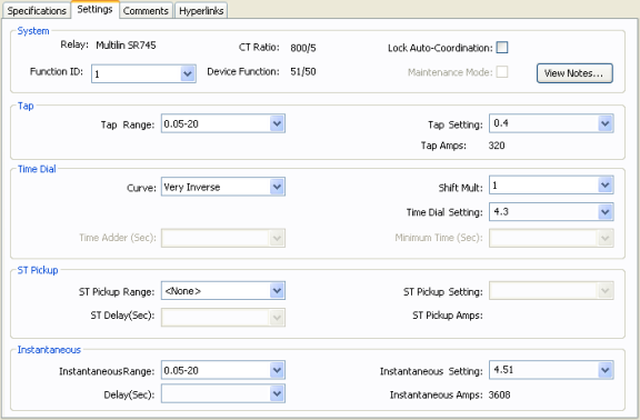
Figure 4: Relay Data - Settings Dialog Box
System: Shows the Function ID, Device Function name and CT Ratio of the device function selected. The values entered in the remaining sections of the Specifications tab are for the device function shown in Function ID field.
Lock AC: Check box to lock Auto Coordination. Any device function with the check box selected will not auto coordinate.
Maintenance Mode: Specifies whether the maintenance mode instantaneous trip switch is on or off for the device function. Some relays might not have a maintenance mode trip switch. When the check box is selected, the TCC can be plotted and arc flash calculation will include the trip time.
View Notes: Click to see notes on the relay. Notes may contain source of data for the relay, specific instructions, or any other pertinent details. Notes are stored in the device data library (stdlib.mdb). You must select a manufacturer and type on the Specifications tab for notes to be available.
Tap: The tap settings or the pickup settings for time-overcurrent function. The name may be relay specific, such as Pickup, I>, and so on.
Tap Range: The range of tap settings which is applicable to the relay. Some relays might have only one range of tap settings, but relays of the same model might come with different tap ranges. In such cases, all possible ranges might be included in a relay type in the library.
Tap Setting: Depending upon the tap range selected, the available tap choices are listed here. The selected tap sets the pickup current.
Tap Amps: The pickup current in the one-line circuit is displayed below Tap Setting.
Time Dial: Selection of type of time-overcurrent curve, and the time dial (delay). This section is name as Time Dial in the library by default. In some cases, for example motor protection relays, they may be called by other names such as Thermal Overload.
Curve: Provides a list of available curves for the device function.
Time Dial Setting: Provides the range of time delays that can be set for the curve selected. Some relays call this time multiplier. In some recloser relays, the time dial (or time multiplier) also affects the instantaneous time delay.
Shift Mult: Shift Multiplier shifts the curve in the vertical direction. This is functionally similar to the time dial and is available in only some relays.
Time Adder: Some relays (mostly recloser relays) have additional time delays to the regular trip curves. This field increases the trip time by the selected value of time in seconds or cycles.
Minimum Time: Some relays (mostly recloser relays) have a minimum time setting. The time-overcurrent function never trips faster than the specified time. In a TCC plot, the curve becomes flat at this time even if the inverse time curve is programmed to trip at faster times.
Instantaneous: The instantaneous pickup range and setting, and time delay are entered in this section. Some relays may have different names for this section, such as Short Circuit Instantaneous, Locked Rotor Instantaneous, and so on. For relays that have both high and low instantaneous settings, it may be necessary to use two device functions.
Instantaneous Range: Provides a list of ranges of instantaneous pickup values applicable to the relay. The Instantaneous settings available depend on the Instantaneous Range selected.
Instantaneous Setting: The instantaneous pickup setting.
Instantaneous Amps: The instantaneous pickup current in the one-line circuit is displayed below Tap Setting.
Instantaneous Delay: Time delay for instantaneous trip.
ST Pickup: Relays with three stage overcurrent relays have the second instantaneous trip with time delay (also called short time in some relays).
ST Pickup Range: Provides a list of ranges of short time or second instantaneous pickup values applicable to the relay. The ST Pickup settings available depend on the ST Pickup Range selected.
ST Pickup Setting: The second instantaneous or shot time pickup setting.
ST Pickup Amps: The instantaneous pickup current in the one-line circuit is displayed below Tap Setting.
ST Delay: Time delay for short time trip.
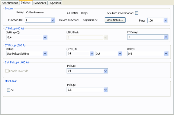
Some relays have settings and time current curves just like the low voltage breaker solid state trip devices. The common type is direct action trip (DAT) units found in some medium voltage breakers. The settings tab for these relays has a slightly different layout as described below.
Plug: Select the rating plug on the trip unit. The sensor is equal to the CT primary amps.

Figure 5: Relay Data – Settings Dialog Box for DAT
LT Pickup: The long time pickup and delay are selected in this section. The pickup calculation depends on the device selected. It may include LTPU Mult, but it will include Setting (C). After the settings are selected, the actual pickup in amperes appears in parentheses.
Setting (C): The long time pickup current setting below which the device will not trip. This is a fraction of the sensor or plug/tap amps. For some trip units LTPU multiple may also be required to set the pickup current.
LTPU Mult: Multiple of Setting (C), which can be adjusted to “fine-tune” the long time pickup setting. Some trip units may not have this feature.
Curve: Some relays may have multiple LT delay curves to choose from. This field enables you to choose the curve shape.

Figure 6: LT Delay Curve
LT Delay: Long time delay setting to select the delay band.
ST Pickup: Short time pickup and delay settings. This section is applicable to only devices with short time trip. After the settings are selected, the actual pickup in amperes appears in parentheses.
Pickup: The short time pickup current setting below which the device will not trip for short time trip. The short time pickup setting may be a multiple of long time pickup, sensor rating, or plug.
(I^x)t: To select shape and slope of delay short time band. When you select In, the (I^x)t function is enabled. The delay band has a slope of minus “x”. When you select Out, the (I^x)t function is disabled, and the short time delay is independent of the current. For some new circuit breakers, the (I^x)t delay may be adjustable. In such case, the choices available are the various possible delay settings.
Delay: Short time delay setting to select the delay band.
Inst Pickup: Nominal instantaneous trip amps, multiple, or pickup setting. When you highlight or select a choice, the corresponding trip amps appear in parenthesis.
Pickup: The instantaneous trip pickup setting.
Enable Override: Selecting Enable Override disables tripping based on the pickup setting. The device trips at an override value that depends on the device style. This feature may or may not be applicable to the device selected.
Maint-Inst: This is the additional instantaneous setting used during maintenance to lower the arc flash hazard. The name of this section may be manufacturer specific such as ARMS, Maint Mode, and so on.
On: Select this check box to indicate the maintenance switch is on. In analysis focus, you can select the breakers and with a right mouse click you can toggle the maintenance mode switch on or off.
Pickup: Setting for maintenance mode trip.
This tab is read-only and appears only if you have imported data from an SKM Data Format file. See Importing an SKM Format File for more information.
See Comments for information.
See Hyperlinks for information.
| Database Technical Reference |