This dialog box includes the following areas and tabs:
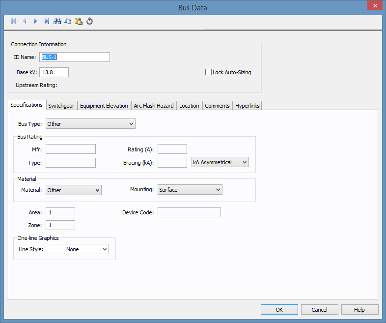
Figure 1: Bus Data Dialog Box
ID Name: Uniquely identifies the bus. This ID name is sometimes referred to as the bus name, and can be up to 16 characters long. The names default to BUS-1, BUS-2, BUS-3, and so on as you enter new buses on the one-line diagram, but you can change those names later if needed.
Base kV: Base kV for the bus. Note that the bus must have a kV entered before equipment can be connected to the bus. Anything less than 1 kV is considered low voltage, anything 1 kV or more is high voltage. MCCs and Panel Schedules can only be connected to low voltage buses.
Lock Auto Sizing: When this check box is selected, the bus cannot be auto-sized.
Upstream Rating: The minimum amp rating of equipment that is upstream from the bus (such as breakers, transformers, or cables). This information is for reference in certain specific configurations of EasyPower and is not generally visible.
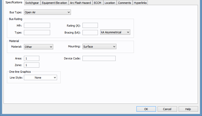
Figure 2: Bus Data Specifications Tab
Bus Type: Type of equipment inside which the bus exists. The bus type definition is important for auto-design and arc flash hazard calculations. In arc flash hazard calculations, the parameters affected by type are the gap between conductors and the distance exponent. The various types are:
Mfr: The manufacturer of the bus. User-defined, up to 15 characters.
Type: The type of bus rating. User-defined, up to 15 characters.
Rating (A): Continuous current rating of the bus in amperes.
Bracing (kA): Short circuit rating of bus bracing in kA. The testing standard unit is specified on the right as follows:
Material: The material with which the bus is made. The options include copper, aluminum, or other.
Mounting: The method by which the bus is mounted. Options include flush, surface, or free standing.
Area: Area numbers are used to uniquely define different areas of the electrical system. These areas can then be used for creating specific text reports from analysis operations that represent subsets of the system. For example, typical paper plant areas may be the power house (Area 1), caustic plant (Area 2), pulp mill (Area 3), and paper machine (Area 4). Area numbers are positive integers between 1 and 999.
Zone: A zone number is simply a sub-area. This enables even more specific reporting. You may want to define the pulp mill as Area 3 and the digester electrical equipment as Zone 2. Specific reports can then be generated for this combination without including the entire pulp mill or the other digesters.
One-line Graphics – Line Style: The box drawn around the bus symbol in the one-line. Any line style can be selected from the box to represent an enclosure such as switchgear.
Device Code: You can type letters or numbers to describe the device code for the bus. The information can be converted and printed as a QR code on arc flash labels.
On DC buses, the base kV defined is not LL nor is it LG. It is a DC average value. If the system you are defining is completely DC with nothing but DC sources, then defining the bus base voltage can be done by finding the rated DC voltage on the gear you are simulating, and then enter it for the bus.
However, if you are simulating a DC system that connects to an AC system through a Rectifier or Inverter, then the proper DC voltage (that works in line with Rectifier and Inverter equations) needs to be specified. For such systems, the DC voltage is related to the AC voltage under no load conditions as follows:
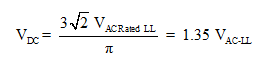
This equation includes the ripple on the DC bus, and is typically used on DC systems that do not include a large smoothing capacitor; systems such as HVDC and simple large rectifiers. If you know that the DC bus includes a DC bus capacitor, and that under loaded conditions ripple is minimal, you should use:
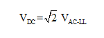
DC Buses that are connected using DC Cables must have the same base kV. Consistency checks are included in the code that should not allow differing kV buses to be connected by a DC Cable.
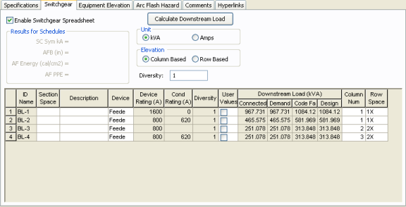
Figure 3: Switchgear Tab of Bus Data Dialog Box
This tab allows you to calculate downstream loads on all the branches breakers connected to the bus. This tab can be labeled as Switchgear, or Panelboard, or Switchboard depending on the Bus Type selected in the Specifications tab.
Enable Switchgear Spreadsheet: Selecting this check box enables you to modify information, enter load data and calculate downstream loads. Once you make the necessary data entry and calculations you can you can clear the check box to prevent changes. When cleared, the data can still be read.
Diversity: Enter the diversity factor for the bus. The factor is used in calculating connected, demand, code, and design kVA. The range is 1 to 10.
Calculate Downstream Load: Clicking this button calculates all downstream loads for each breaker/fuse/branch connected to this bus. All branches are considered downstream unless there exists a source such as UPS, Generator or Utility in the direction of the branch. The program traverses through all the paths and determines whether or not there is a power source in the path. All loads are summed and reported in the spreadsheet if there is no power source in the path.
Unit: You can display downstream loads in kVA or Amps.
Elevation: You can choose the elevation layout of the switchgear such that protective devices in stacked in columns or rows. For volumns, the breakers in one unit are stacked vertically. For rows, you can have a single breakers, or breaker on the left or right. See Elevation View for more information.
ID Name: ID name of the equipment connected to the bus. If any branch has a protective device such as a switch, fuse or breaker connected to the bus, then the ID name of the protective device is reported. Otherwise the branch ID name is reported.
Section Space: Text that describes the space for the protective device or branch.
Description: Text that describes the branch connected to this bus.
Device: You can specify the protective device/branch as Feeder, Main, or Tie. This is for information only and does not affect calculations.
Diversity: The number shown is the diversity factor of the downstream bus with an equipment type of Switchgear, Switchboard, or Panelboard. If another equipment type is selected, the diversity factor is set to 1. Diversity factor is used in calculating the connected, demand, code and design kVA. Press Calculate Downstream Load button to update the diversity factor. The range is from 1 to 10.
Device Rating(A): Continuous current rating of the protective devices in Amps.
Cond Rating (A): Amp rating of branch conductors.
User Values: Select the check box to enable users to enter their own load. When checked, the entered values are used and the calculated downstream values from the one-line are ignored.
For information on this tab, see Elevation View.
The Arc Flash Hazard tab enables you to specify the necessary details of the equipment for arc-flash hazard calculations.
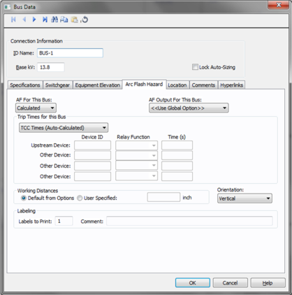
Figure 4: Bus Data Arc Flash Hazard tab
AF For This: Specify how you would like arc flash results determined for this bus. The selections are Calculated, Excluded, or Forced to. Each of these are described below.
When calculated is selected, Trip times for this bus and Working Distances sections become active.
Select method for determining trip times for this bus by choosing on the following:
Specifying working distances shown on one-line and in arc flash hazard report.
Select to exclude the bus from arc-flash reports. Some examples of when excluded might be selected are buses that are on utility side (not worked on by company employees) but still modeled on the one-line and buses where energized work is not likely (splices).
When selected an additional cell will appear. Enter the user-defined incident energy for this bus. The arc flash value incident energy entered for this bus is shown on the one-line and in the Arc Flash Hazard Report. This is typically used for buses where the NFPA-70E has stated a particular PPE level can be assumed if certain conditions exist. Particularly, 208 volt equipment fed by 125 KVA or smaller transformers.
AF Output For This Bus: This specifies whether to display results on the line side or the load side of the Main protective device of the bus equipment. If the arc flash hazards output for this bus needs to be different from the global option, then this field is used. The choices in this box are:
Orientation: This is the orientation of the bus with respect to a worker that may be exposed to arc flash. This is not related to the vertical and horizontal buses in MCC and Switchgear. Arc travels away from the source and extends from the tip of the conductors. Based on the orientation of the conductors, the incident energy can vary. This choice affects the calculations factor (Cf) used in the arc flash hazard equations.
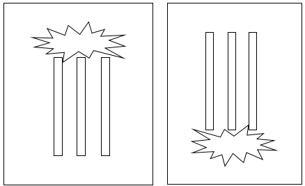
Figure 5: Examples of Vertical orientation
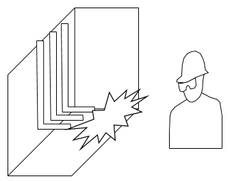
Figure 6: Example of Horizontal Orientation
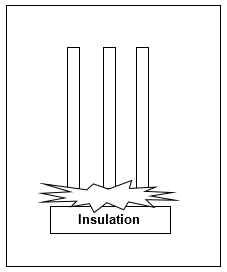
Figure 7: Example of Vertical Into Barrier
Labels to Print: Enter the number of labels you want to print for arc flash hazard analysis. If you enter "0," no labels will print.
Comment: Use to add a comment about the label.
Note: This information is used in certain specific configurations of EasyPower and is not generally visible.
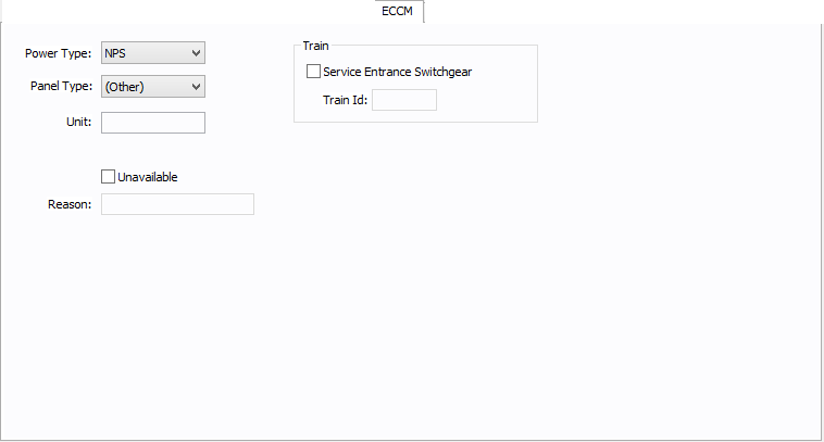
Figure 8: ECCM Tab
Power Type: The power type for the bus. Select from NPS (normal power supply), EPS (emergency power supply), or CPS (critical power supply).
Panel Type: The panel type for the bus. Select from (Other), Tool, Facility, or Tool/Facility. For the bus to be used as a tool point of connection, the type must be Tool or Tool/Facility.
Unit: Use to describe the unit for the bus data (up to 16 characters). You can enter both numbers and letters.
Unavailable: Select to note that this bus is unavailable. You can specify a reason why in the Reason box.
Reason: Use to describe why the bus is unavailable (up to 32 characters). You can enter both numbers and letters.
Service Entrance Switchgear: Select the option to create a train. A train is a redundant power subsystem.
Train ID: The ID for the train. Buses and equipment that are downstream of the service entrance switchgear inherit the train ID from the upstream switchgear.
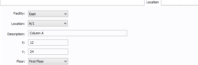
Figure 9: Location Tab
You can specify the location of the equipment on the floor of a building. You can give the location a name, specify the X and Y coordinates of the location, and select a floor.
The coordinates could be measured in feet, for example, or they could represent points on a grid. There are no units associated with the coordinates, so you can use whatever measurement makes sense for you.
Facility: The building in which the equipment is located. Facilities are set up under the Tools > Options arrow under Facilities.
Location: The location of the equipment. This is the combination of the Ref 1 and Ref 2 boxes set up on the location. Locations are set up under the Tools > Options arrow under Locations.
Description: This is a description of the location. The default description comes from the location, but you can change it. You can type up to 32 characters.
X: This is a numeric value (such as feet or grid locations) that represents the horizontal location. The default X value comes from the location, but you can change it.
Y: This is a numeric value (such as feet or grid locations) that represents the vertical location. The default Y value comes from the location, but you can change it.
Floor: Select the floor where the equipment is located. Floors are set up under the Tools > Options arrow under Floors.
For more information, see Facilities, Floors, and Locations.
This tab is read-only and appears only if you have imported data from an SKM Data Format file. See Importing an SKM Format File for more information.
See Comments for information.
See Hyperlinks for information.
| Database Technical Reference |