This dialog box includes the following areas and tabs:
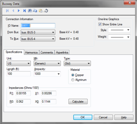
Figure 1: Busway Data Dialog Box
ID Name: Uniquely identifies the busway. This ID name is sometimes referred to as the busway name, and can be up to 12 characters long. The names default to BWY-1, BWY-2, BWY-3, and so on as you enter new busways on the one-line diagram, but you can change those names if needed.
From Bus: The bus from which the busway connects, which must already exist on the one-line. You must be careful that the From Bus has the same base kV as the busway’s To Bus. For your reference, the From Bus base kV is displayed next to the bus name.
To Bus: The bus to which the busway connects, which must already exist on the one-line. You must be careful that the To Bus has the same base kV as the busway’s From Bus. For your reference, the To Bus base kV is displayed next to the bus name.
Show Entire Line: This box is selected by default and causes the entire line to be displayed. By clearing the check box, the line is only shown as a short section at each end with labels indicating the bus to which the other end is attached.
Unit: Select either U.S. or Metric.
Mfr: Provides a list of busway manufacturers available in the device library.
Type: Provides a list of busway types available in the device library.
Length: The length of the busway in feet or meters.
Ampacity: Busway rating in amperes. After you choose a manufacturer and type, the available ampacities are displayed here. If the desired manufacturer is missing from the list, you can select Generic in the Mfr field and (std) in the Type field to select from generic options.
Material: The busway material (copper or aluminum).
Impedances are described in ohms/100 feet or ohms/100 meters. Zero sequence impedances are found from the positive sequence impedance using a Z0/Z1 multiplier from Reference1Let's Be More Specific About Equipment Grounding, R.H. Kaufmann, General Electric Co., GER 1974..
R1: Positive sequence resistance.
X1: Positive sequence reactance.
R0: Zero sequence resistance. If you enter this value as zero (0.0), the positive sequence impedance is used.
X0: Zero sequence reactance. If you enter this value as zero (0.0), the positive sequence impedance is used.
Calculate: Fills in computed values for the impedances R1, X1, R0, and X0 fields. You can override these values by typing in different numbers. The calculations are based on the specific manufacturers’ data for the type of busway chosen with the Mfr, Type, Ampacity, and Material fields.
Use the Harmonics tab to indicate whether this equipment item is introducing harmonics into your power system.
EasyPower offers two methods for calculating RH:
RH = RFund * H R-EXP
RH = RFund * (1+ECF*H2)/(1+ECF)
EasyPower defaults all skin effect correction to R-EXP and a value of 0.5.
| R-EXP | %ECF | |
|---|---|---|
|
Transformer |
0.5-1.0 |
1.0-3.0 |
|
Utility |
0.0-0.8 |
- |
|
Generator |
0.3-0.6 |
- |
|
Line/Cable |
0.5 |
- |
|
Reactor |
0.5-1.0 |
0.8-3.0 |
|
Motor |
0.2-0.4 |
- |
Use to set the fundamental amps. The options are as follows:
To use fundamental current calculated by power flow, select Calculated from Power Flow in the Summation Fundamental Voltage area of the Harmonics Options > Control dialog box.
This tab is read-only and appears only if you have imported data from an SKM Data Format file. See Importing an SKM Format File for more information.
See Comments for information.
See Hyperlinks for information.
| Database Technical Reference |