This dialog box includes the following areas and tabs:
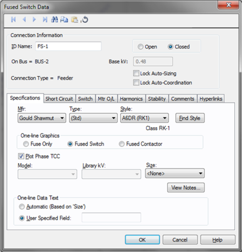
Figure 1: Fused Switch Data Dialog Box
ID Name: Uniquely identifies the fused switch. This ID name is sometimes referred to as the fused switch name, and can be up to 12 characters long. The names default to FS-1, FS-2, FS-3, and so on as you enter new fused switches on the one-line diagram. You can change the ID name as needed.
Open: Normal state of the fused switch. If selected, the one-line displays “OPEN” next to the fused switch symbol.
Closed: If selected, the one-line does not display “OPEN” next to the fused switch symbol.
On Bus: The bus connected to the fuse switch, which must already exist on the one-line.
Base kV: The kV of the bus to which the fuse switch is connected. The options available in the Specifications tab and Short Circuit tab depend on the bus voltage. Either LV or HV fused switches can be selected from this dialog box. Although the EasyPower Device Library has HV and LV Fused Switches as separate devices, the same dialog box is used to select both types.
Connection Type: Whether the fused switch is connected as a “Feeder,” (to a cable, busway, or transformer, for example.) or as a “Tie” (between two buses).
Lock Auto-Sizing: When this check box is selected, the fused switch cannot be auto-sized.
Lock Auto-Coordination: When selected, auto-coordination is not available.
Manufacturer (Mfr): Provides a list of fused switch manufacturers available in the device library. If the desired manufacturer is not listed in the device library, you can add it to the library.
Type: Fused switch types available from the manufacturer chosen in the Mfr field above. If the desired type is not listed, you can add it to the library.
Style: Fused switch styles available from the type chosen in the Type field above. If the desired style is not listed, you can add it to the library.
 Find Style: Enables you to search the library for a fuse style.
One-line Graphics: Select the symbol that appears on the one-line diagram.


Plot Phase TCC: Select this check box to plot the TCC for the fused switch. If the check box is not selected, the TCC for the device is not plotted.
Model: This field enables you to view available models of the fuse style that you have chosen and to select a specific model.
Library kV: Choose the section of the library the fuse data is entered. In most cases, the selected Library kV is approximately the base kV of the fuse. For LV fuses, this field is blank.
Size: This field enables you to view available sizes of the fuse model that you have selected and select a specific size.
View Notes: Click to view notes about the fused switch. You must first select a manufacturer, type, and style. The notes come from the device library.
One-line Data Text: Use to select text to appear on one-line diagram. For text to appear next to symbols on the one-line diagram, choose Tools > Options > Text Visibility and select the check box for Fused Switch.
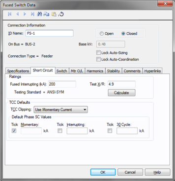
Figure 2: Fused Switch Short Circuit Dialog Box
Fused Interrupting (kA): The interrupting rating of the fused switch.
Test X/R: Test X/R ratio of the circuit. ANSI Standard test ratios might be different for the same fuse depending on the voltage level at which the fuse is applied.
Testing Standard: This comes directly from the device library and cannot be changed.
Calculate: Fills in computed values for the Test X/R and Fused Interrupting fields, based on the device library entry for Mfr, Type, Style, and the base kV. You can override these values by typing in different numbers. This button also causes the appropriate Testing Standard to be displayed for your information.
TCC Defaults: Data entered in this section is used to place tick marks representing short circuit values on the TCC plot.
TCC Clipping: You can clip the time current curve (TCC) for the breaker at the specified current in kA for Momentary (1/2 cycle), 5-cycle or 30-cycle. Select <None> to avoid clipping of TCC.
SC Tick Marks: Select the appropriate check boxes to display the tick mark on the TCC plot. You can display Momentary, Interrupting and 30 Cycle short circuit values. Enter the corresponding short circuit values in kiloamps in their respective edit fields for phase short circuit.
Phase SC Values: The values in kA, entered in these fields can be displayed for phase currents on TCC plots.
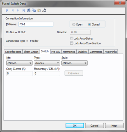
Manufacturer (Mfr): Provides a list of switch manufacturers available in the device library. If the desired manufacturer is not listed in the device library, you can add it to the library.
Type: Switch types available from the manufacturer chosen in the Mfr field above. If the desired type is not listed, you can add it to the library.
Style: Switch styles available from the type chosen in the Type field above. If the desired style is not listed, you can add it to the library.
Cont. Current (A): Continuous current rating of the switch.
Momentary / C&L (kA): Momentary or Close and Latch rating of the switch.
Calculate: Fills in device ratings based on library entries for the specified switch.
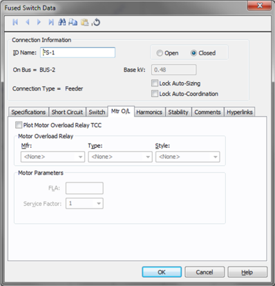
Figure 3: Fused Switch Mtr O/L Dialog Box
Plot Motor Overload Relay TCC: To plot the TCC of an attached motor overload relay with the fused switch TCC, select this check box. If you do not select this check box, then no TCC is plotted for an attached motor overload relay.
Motor Overload Relay: Specify the motor overload relay associated with the breaker in protecting the motor.
Motor Parameters: Determines the pickup level for the motor overload relay.
Full Load Amps (FLA): The full load amps specified for the motor, or the relay rating.
Service Factor: Overload factor of the rated amps. This factor does not increase the rating but simply increases the pickup level. You may enter any value between 1.0 and 1.25.
EasyPower can monitor whether or not the IEEE 519 guideline for harmonics is met at the point of common coupling.
Monitor IEEE 519 Point of Common Coupling: If selected, then the Harmonics Report indicates when this guideline is not being met.
kVA Demand: The kVA Demand.
PCC Isc/Load: The ratio of short circuit current to load current at the point of common coupling.
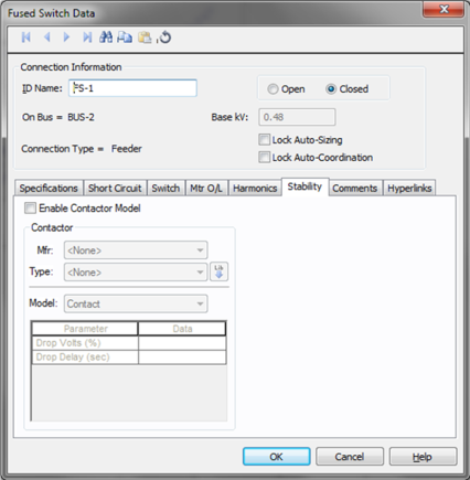
Enable Contactor Model: Enables stability data.
Mfr: Provides a list of contactor manufacturers available in the device library. If the desired manufacturer is not listed in the device library, you can add it to the library.
Type: Contactor types available from the manufacturer chosen in the Mfr field above. If the desired type is not listed, you can add it to the library.
Model: Lists available contactor models in the library.
 Lib: Populates contactor data from the library.
This tab is read-only and appears only if you have imported data from an SKM Data Format file. See Importing an SKM Format File for more information.
See Comments for information.
See Hyperlinks for information.
| Database Technical Reference |