This dialog box includes the following areas and tabs:
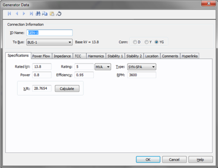
Figure 1: Generator Data Dialog Box
ID Name: Uniquely identifies the generator. This ID name is sometimes referred to as the generator name, and can be up to 12 characters long. The names default to GEN-1, GEN-2, GEN-3, and so on as you enter new generators on the one-line diagram, but you can change those names later if needed.
To Bus: The bus to which the generator connects, which must already exist on the one-line. You must be careful that the To Bus has approximately the same base kV as the generator. For your reference, the To Bus base kV is displayed next to the bus name.
Conn: This specifies the type of connection of the generator windings. This affects the symbol of the generator in the one-line. The options are:
D: Delta connection.………………
Y: Wye connection.……………… 
YG: Wye connection with grounded neutral ……
For wye-grounded connections, you can attach CTs or relays to the ground as shown in the figure below.
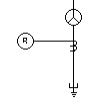
Figure 2: Wye-grounded Connections
kV: Generator rated kV.
MVA: Generator nominal MVA. Generators may be represented as a group or individually.
Type: Generator type. This value is for reference only except for HG and SYN-SP types, which have their momentary reactances determined by X’dv.
Power Factor: Generator operating power factor. This value is for reference only and does not affect analysis.
Efficiency: Generator operating efficiency. This value is for reference only and does not affect analysis.
RPM: Revolutions per minute of the machine. This value is for reference only and does not affect analysis.
X/R: Generator reactance to resistance ratio, which is used to determine resistance values in short circuit studies. Typical range is 30-150 for most generators greater than 10 MVA.
Calculate: Fills in a representative computed value for the X/R field, based on ANSI C37.010. You can override this value by typing in a different number.
GSU Transformer: This field is available only when you configure your system to IEC short circuit. If the generator has a unit substation, then the ID name of the unit transformer is specified in this field. This association is required in order to implement the impedance correction on the generation station unit (GSU) or power station unit (PSU).
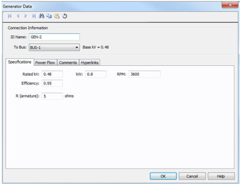
Rated kV: Name plate rated voltage in kV.
kW: Name plate (rated) power in kW.
RPM: Rated speed in revolutions per minute.
Efficiency: Efficiency in per unit.
R (armature): Internal resistance of DC generator in ohms.
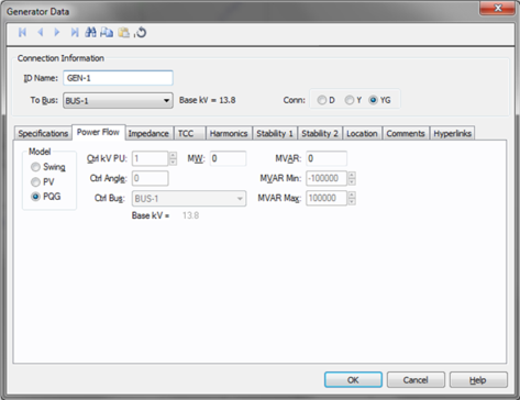
Figure 3: Power Flow tab of Generator Data Dialog Box
Model: Generator bus type used in modeling the power flow simulation. When you select a particular model, those fields that do not apply become unavailable.
Ctl kV PU: Desired control voltage for a regulated generator (PV). The generator will try to control the voltage at the controlled bus to a given value. If the generator bus is the swing bus, this voltage serves as the reference voltage. The voltage is entered in per-unit.
Ctl Angle: Controlled angle is used only when a generator is designated as a swing bus. The value is entered in degrees.
Ctrl Bus: For a PV generator (regulated), the bus that is to be controlled to the control voltage. If this field is blank in the database, EasyPower fills it in with the name of the bus listed in the To Bus field. (Note that this does not take effect until you accept it by choosing OK to close the database dialog box.) This field is ignored if the Model field is set to Swing.
MW: Generator output MW. This may be actual operating or a rated value. This applies only to a PV or PQG generator.
MVAR: Generator output MVAR. This is only used when the generator is a constant power, constant var (PQG) machine or when a PV generator MVAR limit has been reached and the machine automatically switches to PQG.
MVAR Limits: Minimum and maximum MVAR limits for regulated generators (PV). The generator will switch to type PQG if these limits are violated. If there is only one swing generator (Model = “Swing”) on a bus, it should not have any MVAR limits. If there are more than one swing generators on a bus, at least one of them must be unlimited.
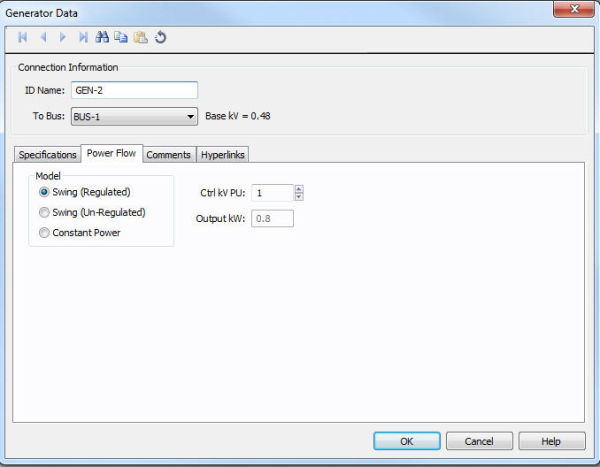
Figure 4: DC Generator Power Flow tab
DC generators have three control modes:
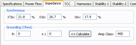
Figure 5: Impedance Tab of Generator Data Dialog Box
X”dv: Subtransient reactance in percent on generators MVA base. Most synchronous generators have subtransient reactances in the 9-20% range1Short Circuit Calculations, General Electric , GET 3550. . The subtransient reactance is used for ½ cycle, 5 cycle and 30 cycle short circuit calculations in accordance with ANSI Standards.
X’dv: Transient reactance in percent on generators MVA base. This value typically ranges from 15-30%. The transient reactance is not used in ANSI standard calculations except for hydro and salient pole generators without amortisseur windings (Xpu = 0.75X’).
X0v: Zero sequence reactance in percent on generators MVA base. This value may range from 3-15% for typical generators. Zero sequence values are used in all ground fault calculations.
Xlr: Locked rotor impedance for induction machines. When actual data is not available, use 16.7%.
Ground R: Generator neutral ground resistance in ohms. This is the most common method of grounding generator neutrals and is usually given in amperes. The impedance is found from the following equation.
R = Vln / I
If the generator is grounded through a grounding transformer with a secondary resistance, this resistance must be converted to the primary winding. If you know the Amp value for the resistor, you can enter the amp value in the Amp Class field and use the Calculate button to find the resistance.
Ground jX: Generator neutral ground reactance in ohms.
Amp Class: This is the current in amps through the ground impedance at the rated voltage. You can enter data in this field directly in Amps or calculate it based on the voltage and ground impedance R +jX using the Calculate button.
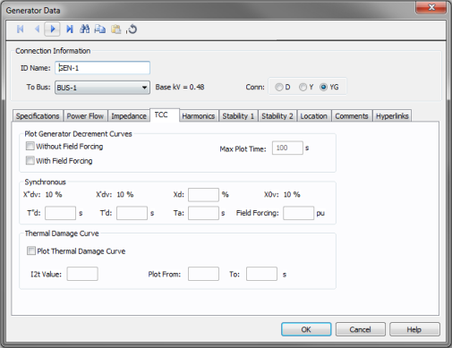
Figure 6: TCC tab of Generator Data dialog
You can plot short circuit decrement curves “with” and “without” excitation field forcing for comparison purposes.
Without Field Forcing: Plots TCC for “without field forcing” option.
With Field Forcing: Plots TCC for “with field forcing” option.
Maximum Plot Time: The amount of time in seconds that the generator can sustain overcurrents without exceeding safe temperature limits.
Xd: Synchronous reactance of the generator, percent.
T”d: Direct axis sub-transient short circuit time constant.
T’d: Direct axis transient short circuit time constant in seconds.
Ta: Armature time constant in seconds.
A typical generator datasheet will provide the Ta value. However, some manufacturers may not provide Ta in the datasheet. The armature time constant is associated with the rate of change of dc current in the stator when the generator is subjected to a 3-phase fault. Ta for different types of generators is provided in the book “Power System Control and Stability,” by Paul M. Anderson and A. A. Fouad, IEEE Press, 1994.
Ta = (Ld’ + Lq) / 2r
Where Ld’ is the d axis transient inductance and Lq is q axis inductance. A typical value of Ta is 0.15 seconds for fault on the machine terminal.
Prabha Kundur’s book “Power System Stability and Control”, McGraw-Hill, 1994, provides the following equation for Ta:
Ta = (Ld” + Lq”) / 2/ Ra
Typical value for Ta lies between 0.03 and 0.35s.
Forcing Field: Forced excitation current at a given load expressed as per unit value of field current at no load, Ifd0.
This section allows you to plot “I^2t” thermal damage curve for the generator.
Plot Thermal Damage Curve: Select this check box to enable plotting of the damage curve and to enter data for this section.
I2t Value: This defines the (I^2)t line for the damage curve. I is in per-unit of generator rated current and t is in seconds. If I2t Value is 20, then the extrapolated damage curve line would intersect with the FLA of the generator at 20 seconds.
Plot From/To: The damage curve is drawn on the TCC plot within these values as the lower and upper limits in seconds.
Use the Harmonics tab to indicate whether this equipment item is introducing harmonics into your power system.
EasyPower offers two methods for calculating RH:
RH = RFund * H R-EXP
RH = RFund * (1+ECF*H2)/(1+ECF)
EasyPower defaults all skin effect correction to R-EXP and a value of 0.5.
| R-EXP | %ECF | |
|---|---|---|
|
Transformer |
0.5-1.0 |
1.0-3.0 |
|
Utility |
0.0-0.8 |
- |
|
Generator |
0.3-0.6 |
- |
|
Line/Cable |
0.5 |
- |
|
Reactor |
0.5-1.0 |
0.8-3.0 |
|
Motor |
0.2-0.4 |
- |
Use to set the fundamental amps. The options are as follows:
To use fundamental current calculated by power flow, select Calculated from Power Flow in the Summation Fundamental Voltage area of the Harmonics Options > Control dialog box.
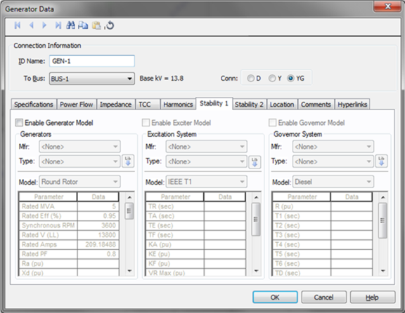
Enable Generator Model: Enables stability data entry for Generator Model.
Mfr: Provides a list of generator manufacturers available in the device library. If the desired manufacturer is not listed in the device library, you can add it to the library.
Type: Generator types available from the manufacturer chosen in the Mfr field above. If the desired type is not listed, you can add it to the library.
Model: Lists available generator models in the library.
 Lib: Populates generator data from the library.
Enable Exciter Model: Enables stability data entry for Exciter Model.
Mfr: Provides a list of exciter manufacturers available in the device library. If the desired manufacturer is not listed in the device library, you can add it to the library.
Type: Exciter types available from the manufacturer chosen in the Mfr field above. If the desired type is not listed, you can add it to the library.
Model: Lists available exciter models in the library.
Lib: Populates exciter data from the library.
Enable Governor Model: Enables stability data entry for Governor Model.
Mfr: Provides a list of governor manufacturers available in the device library. If the desired manufacturer is not listed in the device library, you can add it to the library.
Type: Governor types available from the manufacturer chosen in the Mfr field above. If the desired type is not listed, you can add it to the library.
Model: Lists available governor models in the library.
Lib: Populates governor data from the library.
For details on the parameters, see Dynamic Stability .
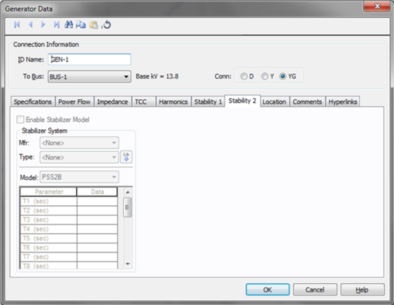
Enable Stabilizer Model: Enables stability data entry for Stabilizer Model.
Mfr: Provides a list of stabilizer manufacturers available in the device library. If the desired manufacturer is not listed in the device library, you can add it to the library.
Type: Stabilizer types available from the manufacturer chosen in the Mfr field above. If the desired type is not listed, you can add it to the library.
Model: Lists available stabilizer models in the library.
Lib: Populates stabilizer data from the library.
For details on the parameters, see Dynamic Stability .
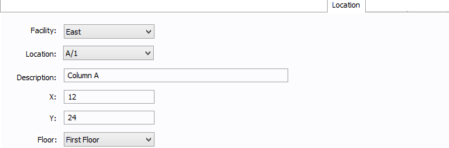
Figure 7: Location Tab
You can specify the location of the equipment on the floor of a building. You can give the location a name, specify the X and Y coordinates of the location, and select a floor.
The coordinates could be measured in feet, for example, or they could represent points on a grid. There are no units associated with the coordinates, so you can use whatever measurement makes sense for you.
Facility: The building in which the equipment is located. Facilities are set up under the Tools > Options arrow under Facilities.
Location: The location of the equipment. This is the combination of the Ref 1 and Ref 2 boxes set up on the location. Locations are set up under the Tools > Options arrow under Locations.
Description: This is a description of the location. The default description comes from the location, but you can change it. You can type up to 32 characters.
X: This is a numeric value (such as feet or grid locations) that represents the horizontal location. The default X value comes from the location, but you can change it.
Y: This is a numeric value (such as feet or grid locations) that represents the vertical location. The default Y value comes from the location, but you can change it.
Floor: Select the floor where the equipment is located. Floors are set up under the Tools > Options arrow under Floors.
For more information, see Facilities, Floors, and Locations.
This tab is read-only and appears only if you have imported data from an SKM Data Format file. See Importing an SKM Format File for more information.
See Comments for information.
See Hyperlinks for information.
| Database Technical Reference |