This dialog box includes the following areas and tabs:
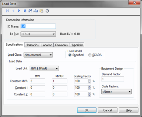
Figure 1: Load Data Dialog Box
ID Name: Uniquely identifies the lumped load. This ID name is sometimes referred to as the load name, and can be up to 16 characters long. The names default to L-1, L-2, L-3, and so on as you enter new loads on the one-line diagram, but you can change those names if needed.
To Bus: The bus the load connects to, which must already exist on the one-line. For your reference, the To Bus base kV is displayed next to the bus name.
Load Class: To specify the class of in terms of importance. You can select Essential, Critical, or Non-essential. This field does not affect analysis. It can be used in database query to distinguish a certain load class from others. See Advanced Query.
Specified: Designates the Load Data field to a user-entered model. You can enter any combination of constant kVA, constant I, or constant Z load.
SCADA: Designates the Load Data field to an imported real-time SCADA model. Data can also be user input in the SCADA fields just like Specified data.
Any combination of constant kVA, constant current, or constant impedance loads may be modeled. Different types of loads can also be mixed and matched to model a specific type of equipment such as variable speed drives.
Load Unit: Specifies the units that will be used for load data. Use the box to choose the unit.
Constant kVA/MVA: Constant kVA load entered in MW and MVAR. Note that the term “constant kVA” seems to be an industry standard even though MVA seems to be the more common unit for large industrial uses. See also Notes on Power Factor.
Constant I: Constant current load given in MW and MVAR. These values should be entered in 1.0 per-unit volts.
Constant Z: Constant impedance load given in MW and MVAR. These values should be entered in 1.0 per-unit volts.
Scaling Factor: Each load can be varied by applying a different scaling factor. This lets you model the actual panel or lumped load on a bus, then study different loading conditions. This allows quick “what if” studies and prevents errors that occur from data entry.
Demand Factor: Demand factor for the load.
Code Factors: NEC code factor for the load.
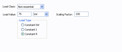
Figure 2: DC Load Specifications
Load Class: To specify the class of in terms of importance. You can select Essential, Critical, or Non-essential. This field does not affect analysis. It can be used in database query to distinguish a certain load class from others.
Load Value: Rated load in kW or Amps.
Scaling Factor: Ratio of actual load to rated load in percent. This is used in power flow calculations.
Load Type: Choose one of the following types:
Constant kW: The kW consumed remains constant even when terminal voltage changes.
Constant I: Constant current is drawn by the load even when terminal voltage changes.
Constant R: The resistance is constant, so the kW and current will vary based on the terminal voltage.
Use the Harmonics tab to indicate whether this equipment item is introducing harmonics into your power system.
The default is Linear, indicating the equipment does not produce harmonics. Choosing Harmonic makes the item an harmonic source and makes other fields in this tab available to edit.
Note:
For an adjustable frequency drive (AFD), the Load Type is always Harmonic.
For motors, the Load Type is Harmonic if the With Adjustable Frequency Drive (AFD) check box is selected on the Specifications tab of the motor; otherwise, it is always Linear.
Use the spreadsheet to enter the harmonic spectrum produced by this item. You can enter up to 30 different harmonics in each equipment item. In the spreadsheet, enter the Harmonic Number (such as 5 for the 5th harmonic), the Harmonic Current in percent of the Fundamental Amps, and the Current Angle. By indicating the current angle, you can simulate transformer phase shift effects on rectifiers so appropriate canceling can take place. The harmonic may be integer or non-integer.
Common harmonic spectra may be entered from the device library. For instructions on how to enter your own spectra information, see Harmonics with Spectrum™. After selecting a particular device library spectrum from the Mfr and Type lists, click Import, and that spectrum is entered into the harmonic spreadsheet.
EasyPower offers two methods for calculating RH:
RH = RFund * H R-EXP
RH = RFund * (1+ECF*H2)/(1+ECF)
EasyPower defaults all skin effect correction to R-EXP and a value of 0.5.
| R-EXP | %ECF | |
|---|---|---|
|
Transformer |
0.5-1.0 |
1.0-3.0 |
|
Utility |
0.0-0.8 |
- |
|
Generator |
0.3-0.6 |
- |
|
Line/Cable |
0.5 |
- |
|
Reactor |
0.5-1.0 |
0.8-3.0 |
|
Motor |
0.2-0.4 |
- |
Use to set the fundamental amps. The options are as follows:
To use fundamental current calculated by power flow, select Calculated from Power Flow in the Summation Fundamental Voltage area of the Harmonics Options > Control dialog box.
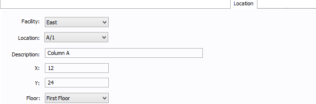
Figure 3: Location Tab
You can specify the location of the equipment on the floor of a building. You can give the location a name, specify the X and Y coordinates of the location, and select a floor.
The coordinates could be measured in feet, for example, or they could represent points on a grid. There are no units associated with the coordinates, so you can use whatever measurement makes sense for you.
Facility: The building in which the equipment is located. Facilities are set up under the Tools > Options arrow under Facilities.
Location: The location of the equipment. This is the combination of the Ref 1 and Ref 2 boxes set up on the location. Locations are set up under the Tools > Options arrow under Locations.
Description: This is a description of the location. The default description comes from the location, but you can change it. You can type up to 32 characters.
X: This is a numeric value (such as feet or grid locations) that represents the horizontal location. The default X value comes from the location, but you can change it.
Y: This is a numeric value (such as feet or grid locations) that represents the vertical location. The default Y value comes from the location, but you can change it.
Floor: Select the floor where the equipment is located. Floors are set up under the Tools > Options arrow under Floors.
For more information, see Facilities, Floors, and Locations.
This tab is read-only and appears only if you have imported data from an SKM Data Format file. See Importing an SKM Format File for more information.
See Comments for information.
See Hyperlinks for information.
| Database Technical Reference | |
| Notes on Power Factor |