This dialog box includes the following areas and tabs:
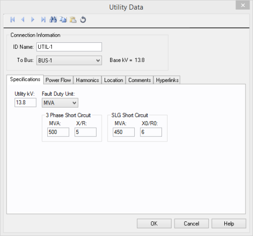
Figure 1: Utility Data Dialog Box
ID Name: Uniquely identifies the utility. This ID name is sometimes referred to as the utility name, and can be up to 12 characters long. The names default to UTIL-1, UTIL-2, UTIL-3, and so on as you enter new utilities on the one-line diagram, but you can change those names later if needed.
To Bus: The bus the utility connects to, which must already exist on the one-line. For reference, the To Bus base kV is displayed next to the bus name.
Utility kV: Utility operating kV for calculation of per-unit impedance. This does not affect the power flow controlled voltage.
Fault Duty Unit: Specifies the unit in which the short circuit information is entered. Any of the four following units may be selected.
| Fault Duty | Unit Name | Short Circuit Units |
|---|---|---|
| MVA | MVA | X/R |
| kA | kA | X/R |
| Ohms | R | jX |
| Zpu | Rpu | jXpu |
Utility MVA Base: When Zpu is selected as the fault duty unit, you also need to specify the MVA Base of the utility for the per unit values.
3-Phase Short Circuit MVA: Utility 3-phase short circuit MVA. Used in determining short circuit reactance values.
3-Phase Short Circuit X/R: Utility reactance to resistance ratio for a three-phase bolted fault (positive sequence impedance). Used in determining the resistance value in short circuit studies.
SLG Short Circuit MVA: Utility line to ground short circuit MVA. Used in determining short circuit reactance values. This value is calculated using:
MVASLG=SQRT(3)VLLI1ph
SLG Short Circuit X/R: Utility zero sequence reactance to resistance ratio. Used in determining the resistance value in short circuit studies.
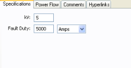
Figure 2: DC Utility Specifications
kV: DC Utility operating kV. If this value is different than the bus base kV, then the controlled voltage is scaled appropriately.
Fault Duty: Expected fault value (in Amperes) or the Thevenin equivalent resistance (in ohms) at the DC utility connection point.
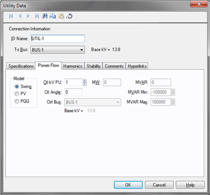
Figure 3: Power Flow Tab of Utility Data Dialog Box
Model: Utility bus type used in modeling the power flow simulation. When you choose a particular model, those fields which do not apply become unavailable. A utility is normally modeled as the reference or swing bus, but may be modeled as another generator bus. See Swing Sources for more information.
MW: Utility output MW. This may be actual operating or a rated value. This applies only to a PV or PQG utility.
MVAR: Utility output MVAR. This is only used when the utility is a constant power, constant var (PQG) machine, or when a PV utility MVAR limit has been reached and the machine automatically switches to PQG.
MVAR Limits: Minimum and maximum MVAR limits for regulated utilities (PV). The utility will switch to type PQG if these limits are violated. If there is only one swing utility (Model = Swing) on a bus, it should not have any MVAR limits. If there is more than one swing utility on a bus, at least one of them must be unlimited.
Ctl kV PU: Desired control voltage for a regulated utility (PV). The utility will try to control the voltage at the controlled bus to a given value. If the utility bus is the swing bus, this voltage serves as the reference voltage. The voltage is entered in per-unit.
Ctl Angle: Controlled angle is used only when a utility is designated as a swing bus. The value is entered in degrees.
Ctrl Bus: For a PV utility (regulated), the bus that is to be controlled to the control voltage. If this field is blank in the database, EasyPower fills it in with the name of the bus listed in the To Bus field. (This does not take effect until you click OK to close the database dialog box.) This field is ignored if the Model field is set to Swing.
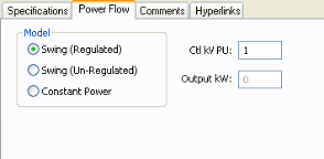
Figure 4: DC Utility Power Flow Tab
The power flow can be one of the following models:
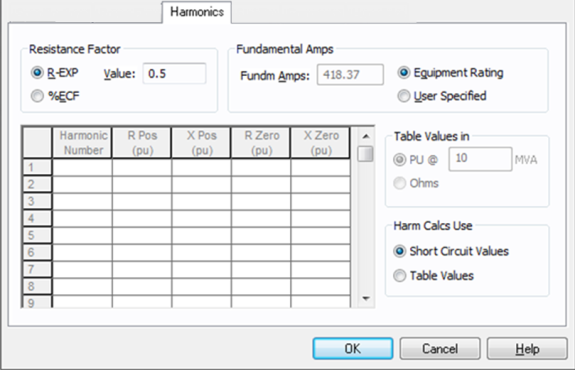
Figure 5: Harmonics Tab of Utility Data Dialog Box
EasyPower offers two methods for calculating RH:
RH = RFund * H R-EXP
RH = RFund * (1+ECF*H2)/(1+ECF)
EasyPower defaults all skin effect correction to R-EXP and a value of 0.5.
| R-EXP | %ECF | |
|---|---|---|
|
Transformer |
0.5-1.0 |
1.0-3.0 |
|
Utility |
0.0-0.8 |
- |
|
Generator |
0.3-0.6 |
- |
|
Line/Cable |
0.5 |
- |
|
Reactor |
0.5-1.0 |
0.8-3.0 |
|
Motor |
0.2-0.4 |
- |
Use to set the fundamental amps. The options are as follows:
To use fundamental current calculated by power flow, select Calculated from Power Flow in the Summation Fundamental Voltage area of the Harmonics Options > Control dialog box.
Table Values in: When the frequency response of the utility is specified in the table (spreadsheet), the impedance can be in per-unit of a specified MVA or in Ohms.
Harm Calcs Use: The utility response to harmonics can be based on the impedance calculated from short circuit values in the Specifications tab or based on the table.
Harmonic Table: If Tables Values is selected for Harm Calcs Use, then this table is available. For each harmonic number you can enter the impedances: R Pos, X Pos, R Zero and X Zero. For each harmonic number entered in the spreadsheet the row must be complete with data. The harmonic may be integer or non-integer.
This tab is read-only and appears only if you have imported data from an SKM Data Format file. See Importing an SKM Format File for more information.
See Comments for information.
See Hyperlinks for information.
| Database Technical Reference |