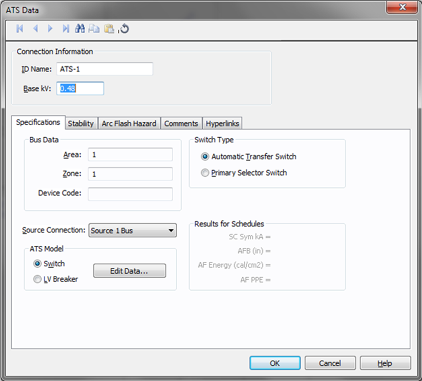
Figure 1: ATS Data Dialog Box
This dialog box includes the following areas and tabs:
Figure 1: ATS Data Dialog Box
| Option | Description |
|---|---|
| ID Name | Uniquely identifies the automatic transfer switch (ATS). This can be up to 16 characters long. The names default to ATS-1, ATS-2, ATS-3... as you enter new ATSs on the one-line, but you can change those names to make them more descriptive if needed. |
| Base kV | Base kV for the ATS. An ATS has three buses as shown by the nodes in the symbol. Note that the bus must have a kV entered before equipment can be connected to the bus. Anything less than 1kV is considered low voltage, anything 1kV or more is high voltage. |
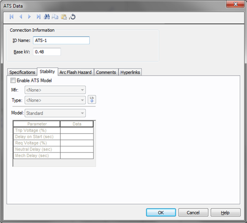
Figure 2: Stability Tab
| Option | Description |
|---|---|
| Enable ATS Model | Select the check box to enter stability information. |
| Manufacturer (Mfr) | Provides a list of ATS manufacturers available in the device library. If the desired manufacturer is not listed in the device library, you can add it to the library. |
| Type | ATS types available from the manufacturer chosen in the Mfr field above. If the desired type is not listed, you can add it to the library. |
| Model | ATS models available from the type chosen in the Type field above. If the desired style is not listed, you can add it to the library. |
 Lib Lib |
Populates ATS data from the library. |
See EasyPower Device Library for more information.
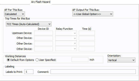
Figure 3: Arc Flash Hazard Tab
| Option | Description |
|---|---|
| AF For This Bus |
Specify how you would like arc flash results determined for this bus. Calculated: When calculated is selected, Trip times for this bus and Working Distances sections become available. Excluded: Select to exclude the bus from arc-flash reports. Some examples of when excluded might be selected are buses that are on utility side (not worked on by company employees) but still modeled on the one-line and buses where energized work is not likely (splices). Forced To: When selected an additional cell will appear where you can enter the incident energy for this bus. The arc flash value incident energy entered for this bus is shown on the one-line and in the Arc Flash Hazard Report. This is typically used for buses where the NFPA-70E has stated a particular PPE level can be assumed if certain conditions exist. Particularly, 208 volt equipment fed by 125 KVA or smaller transformers. |
| AF Output For This Bus |
This specifies whether to display results on the line side or the load side of the Main protective device of the bus equipment. If the arc flash hazards output for this bus needs to be different from the global option, use this field. The choices are:
|
| Trip Times for this Bus |
Select method for determining trip times for this bus by choosing on the following:
|
| Working Distances |
Specifies the working distances shown on the one-line and in the arc flash hazard report.
|
| Orientation |
This is the orientation of the bus with respect to a worker that may be exposed to arc flash. This is not related to the vertical and horizontal buses in MCC and Switchgear. Arc travels away from the source and extends from the tip of the conductors. Based on the orientation of the conductors, the incident energy can vary. This choice affects the calculations factor (Cf) used in the arc flash hazard equations. See Orientation for more information. |
| Labels to Print | Enter the number of labels you want to print for arc flash hazard analysis. If you enter "0," no labels will print. |
| Comment | Use to add a comment to the arc flash label. |
See Location for more information.
This tab is read-only and appears only if you have imported data from an SKM Data Format file. See Importing an SKM Format File for more information.
See Comments for information.
See Hyperlinks for information.
| Database Technical Reference | |
| EasyPower Device Library |
|
|