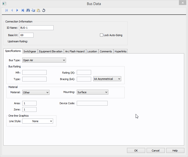
Figure 1: Bus Data Dialog Box
This dialog box includes the following areas and tabs:
For DC buses, see also DC Bus - Base Voltage Specifications.
Figure 1: Bus Data Dialog Box
| Option | Description |
|---|---|
| ID Name | Uniquely identifies the bus. This name can be up to 16 characters long. The names default to BUS-1, BUS-2, BUS-3... as you enter new buses on the one-line, but you can change those names to make them more descriptive if needed. |
| Base kV |
Base kV for the bus. Note that the bus must have a kV entered before equipment can be connected to the bus. Anything less than 1 kV is considered low voltage, anything 1 kV or more is high voltage. MCCs and panel schedules can only be connected to low voltage buses. For DC buses, see also DC Bus - Base Voltage Specifications. |
| Lock Auto Sizing | When this check box is selected, the bus cannot be auto-sized. |
| Upstream Rating |
The minimum amp rating of equipment that is upstream from the bus (such as breakers, transformers, or cables). This information is for reference in certain specific configurations of EasyPower and is not generally visible. |
This tab allows you to calculate downstream loads on all the branches breakers connected to the bus. This tab can be labeled as Switchgear, or Panelboard, or Switchboard depending on the Bus Type selected in the Specifications tab.
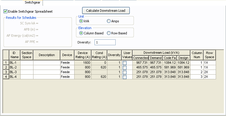
Figure 2: Switchgear Tab of Bus Data Dialog Box
| Option | Description |
|---|---|
| Enable Switchgear Spreadsheet | Selecting this check box enables you to modify information, enter load data and calculate downstream loads. Once you make the necessary data entry and calculations you can you can clear the check box to prevent changes. When the check box is not selected, the data can still be read, but not changed. |
| Calculate Downstream Load | Clicking this button calculates all downstream loads for each breaker/fuse/branch connected to this bus. All branches are considered downstream unless there exists a source such as a UPS, generator or utility in the direction of the branch. The program traverses through all the paths and determines whether or not there is a power source in the path. All loads are summed and reported in the spreadsheet if there is no power source in the path. |
| Unit | You can display downstream loads in kVA or Amps. |
| Elevation | You can choose the elevation layout of the switchgear such that protective devices in stacked in columns or rows. For columns, the breakers in one unit are stacked vertically. For rows, you can have a single breakers, or breaker on the left or right. See Elevation View for more information. |
| Diversity | Enter the diversity factor for the bus. The factor is a divisor used in calculating connected, demand, code, and design kVA. The diversity factor is the ratio of the sum of the maximum demands of the individual loads to the maximum demand of the entire system, include all of those loads. Enter a value of 1 or greater. |
| Spreadsheet Column Headings | |
| ID Name | ID name of the equipment connected to the bus. If any branch has a protective device such as a switch, fuse or breaker connected to the bus, then the ID name of the protective device is shown. Otherwise the branch ID name is shown. |
| Section Space | Text that describes the space for the protective device or branch. |
| Description | Text that describes the branch connected to this bus. |
| Device | You can specify the protective device/branch as Feeder, Main, or Tie. This is for information only and does not affect calculations. |
| Diversity |
The number shown is the diversity factor of the downstream bus with an equipment type of Switchgear, Switchboard, or Panelboard. If another equipment type is selected, the diversity factor is set to 1. Diversity factor is used in calculating the connected, demand, code and design kVA. The diversity factor is the ratio of the sum of the maximum demands of the individual loads to the maximum demand of the entire system, include all of those loads. Click Calculate Downstream Load to update the diversity factor. |
| Device Rating(A) | Continuous current rating of the protective devices in amps. |
| Cond Rating (A) | Amp rating of branch conductors. |
| User Values | Select the check box to manually enter a load. When checked, the entered values are used and the calculated downstream values from the one-line are ignored. |
For information on this tab, see Elevation View.
The Arc Flash Hazard tab enables you to specify the necessary details of the equipment for arc-flash hazard calculations.
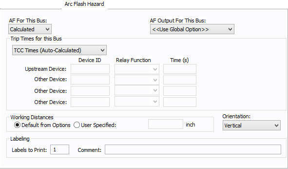
Figure 3: Arc Flash Hazard Tab
| Option | Description |
|---|---|
| AF For This Bus |
Specify how you would like arc flash results determined for this bus. Calculated: When calculated is selected, Trip times for this bus and Working Distances sections become available. Excluded: Select to exclude the bus from arc-flash reports. Some examples of when excluded might be selected are buses that are on utility side (not worked on by company employees) but still modeled on the one-line and buses where energized work is not likely (splices). Forced To: When selected an additional cell will appear where you can enter the incident energy for this bus. The arc flash value incident energy entered for this bus is shown on the one-line and in the Arc Flash Hazard Report. This is typically used for buses where the NFPA-70E has stated a particular PPE level can be assumed if certain conditions exist. Particularly, 208 volt equipment fed by 125 KVA or smaller transformers. |
| AF Output For This Bus |
This specifies whether to display results on the line side or the load side of the Main protective device of the bus equipment. If the arc flash hazards output for this bus needs to be different from the global option, use this field. The choices are:
|
| Trip Times for this Bus |
Select method for determining trip times for this bus by choosing on the following:
|
| Working Distances |
Specifies the working distances shown on the one-line and in the arc flash hazard report.
|
| Orientation |
This is the orientation of the bus with respect to a worker that may be exposed to arc flash. This is not related to the vertical and horizontal buses in MCC and Switchgear. Arc travels away from the source and extends from the tip of the conductors. Based on the orientation of the conductors, the incident energy can vary. This choice affects the calculations factor (Cf) used in the arc flash hazard equations. See Orientation for more information. |
| Labels to Print | Enter the number of labels you want to print for arc flash hazard analysis. If you enter "0," no labels will print. |
| Comment | Use to add a comment to the arc flash label. |
Note: This information is used in certain specific configurations of EasyPower and is not generally visible.
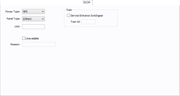
Figure 4: ECCM Tab
| Option | Description |
|---|---|
| Power Type |
The power type for the bus. Select from:
|
| Panel Type |
The panel type for the bus. Select from:
For the bus to be used as a tool point of connection, the type must be Tool or Tool/Facility. |
| Unit | Use to describe the unit for the bus data (up to 16 characters). You can enter both numbers and letters. |
| Unavailable | Select to note that this bus is unavailable. You can specify a reason why in the Reason box. |
| Reason | Use to describe why the bus is unavailable (up to 32 characters). You can enter both numbers and letters. |
| Train | |
| Service Entrance Switchgear | Select the option to create a train. A train is a redundant power subsystem. |
| Train ID | The ID for the train. Buses and equipment that are downstream of the service entrance switchgear inherit the train ID from the upstream switchgear. |
See Location for more information.
This tab is read-only and appears only if you have imported data from an SKM Data Format file. See Importing an SKM Format File for more information.
See Comments for information.
See Hyperlinks for information.
| Database Technical Reference | |
| DC Bus - Base Voltage Specifications |
|
|