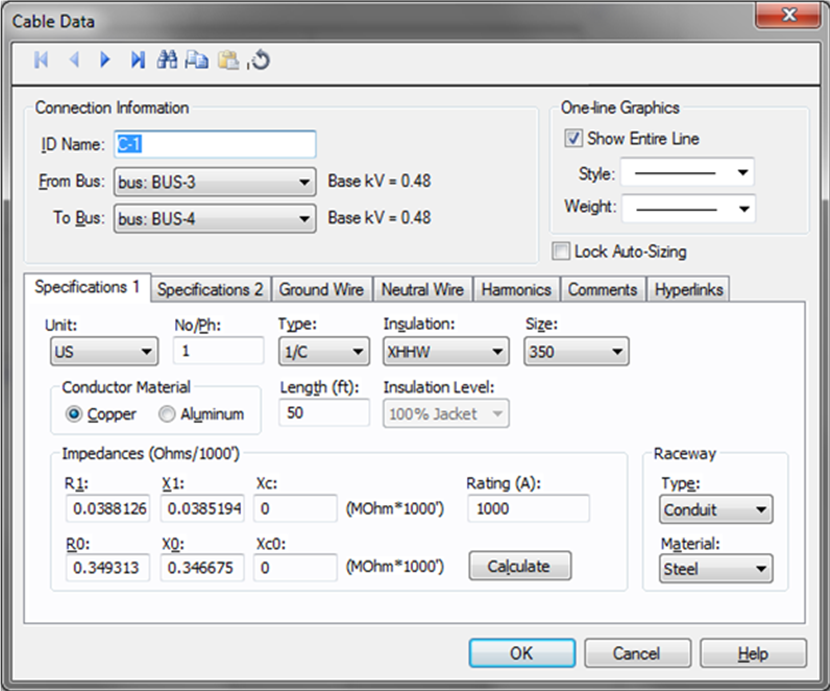
Figure 1: Cable Data Dialog Box (AC Cable)
This dialog box includes the following areas and tabs:
Figure 1: Cable Data Dialog Box (AC Cable)
| Option | Description |
|---|---|
| Unit | Choose either U.S., CSA, Metric or Per Unit. If you choose Per Unit, all fields except those in the Impedance (PU) section become unavailable. |
| No/Phase | Total number of cables modeled. The default of one (1) means one conductor per phase. Two (2) means two conductors in parallel per phase, and so on. When two or more conductors are in parallel, the impedance of the circuit is decreased by that factor. The impedances shown in the dialog box are for one conductor only, and are not based on the No./Phase field, so if you enter these values instead of using Calculate, make sure they are for one conductor only. This lets you easily check handbook values without additional arithmetic. The per-unit impedances listed in a database report considers the total number of conductors. |
| Type |
Five different cable types can be modeled. Cable type is used in determining the impedance of the conductor.
Note: For Teck cables, select the CSA unit. For single conductor Teck, select 1/C and for 3-conductor Teck, select IAA for aluminum armor or IAS for steel armor. Look for Teck or Teck-90 in the Insulation type. |
| Insulation |
US Low Voltage Insulation (1000 volts or less):
US High Voltage Insulation (Over 1000 volts):
|
| Size | Conductor size in AWG, MCM, or mm2. Cable size is used in determining the impedance of the conductor. |
| Conductor Material | The conductor material (copper or aluminum). |
| Length | Length of the cable in feet or meters. |
| Impedances | |
| Impedances are described as Ohms/1000 feet, Ohms/KM or PU. Zero sequence impedances are described as the positive sequence impedance using a Z0/Z1 multiplier by Kaufmann1Let's Be More Specific About Equipment Grounding, R.H. Kaufmann, General Electric Co., GER 1974, specifically, on page 7. | |
| R1 | Positive sequence resistance. |
| X1 | Positive sequence reactance. |
| R0 | Zero sequence resistance. If you enter this value as zero (0.0), the positive sequence impedance is used. |
| X0 | Zero sequence reactance. If you enter this value as zero (0.0), the positive sequence impedance is used. |
| Rating | Conductor rating in amperes. If you use Calculate, this value is retrieved from the device library and is for one conductor. You need to input the proper rating. The 75(C) rating is shown, to indicate lug ratings, below the rating field if calculate is used to determine the rating (low voltage only). You can derate cable amp rating based on ambient temperature and the number of conductors in conduits or raceways by specifying the Ambient Temp and the Duct Config field in the Specification 2 tab of the dialog box. For the Ambient Temp derating to take effect, you need to specify the derating standard in Tools > Options > Equipment. |
| Calculate | Fills in computed values for the R1, X1, R0, X0, Xc, Xc0,and Rating (A) fields. You can override these values by typing in your own numbers. The calculations are based on the cable specifications and the type of ground circuit2General Electric Wire and Cable Handbook, March 31 1983. |
| Raceway Configuration | |
| Type |
Medium in which the conductor is supported or run (conduit, cable tray, air, or direct buried). If none is selected, the cable ampacity defaults to 10A. Note: For buried conduits, you can apply the derating for ampacity in the Duct Config field on the Specifications 2 tab. |
| Material | Raceway material, which can be either metallic such as steel, or non-metallic such as aluminum, PVC, IMT, or EMT. This value is used in determining reactances. |
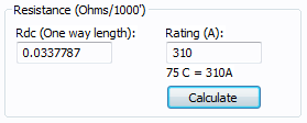
Figure 2: DC Resistance Specification
| Option | Description |
|---|---|
| Rdc (One way length) | The DC resistance of the cable, specified in Ohms per 1000 feet and as the one way (not out and back) value. (Not applicable for AC cables.) |
| Rating (A) | Ampacity of the DC Cable. |
Note: Doubling of Cable Length—Since DC systems are not “balanced,” cable runs need to simulate the total out and back DC resistance. Thus, internally, all DC line lengths are doubled to properly simulate the total voltage drop correctly.
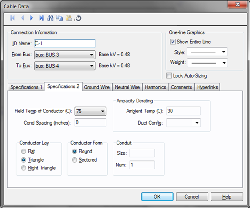
Figure 3: Specifications 2 Tab of the Cable Data Dialog Box (AC Cable Shown)
Note: All fields have a substantial effect on conductor impedances when using the Calculate button.
| Description | Option |
|---|---|
| Field Temp of Conductor (C) |
Temperature of the loaded conductor. This can be varied from 25C to 250C depending on the type of study being performed. Cable temperature is used in determining the resistance of the conductor. The resistance increases with the conductor temperature. Note: This is not the ambient air temperature or the ground temperature. |
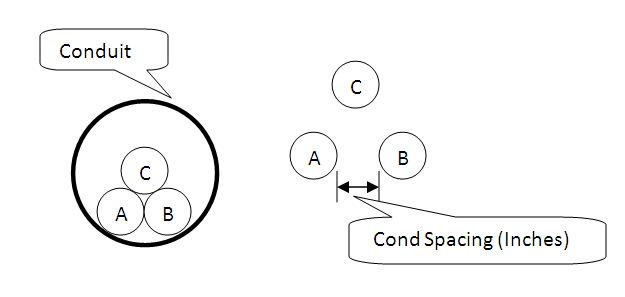
| Cond Spacing |
Distance between the outside insulation or jacket edges of adjacent phase conductors. This will affect the reactance calculations. All three spacings are modeled as the same or as a GMD equivalent. Note: This is not the center to center distance. See figure below.
Figure 4: Conductor Spacing: Zero Spacing (Left) and With Spacing (Right) |
|
Ampacity Derating |
|
| Duct Config |
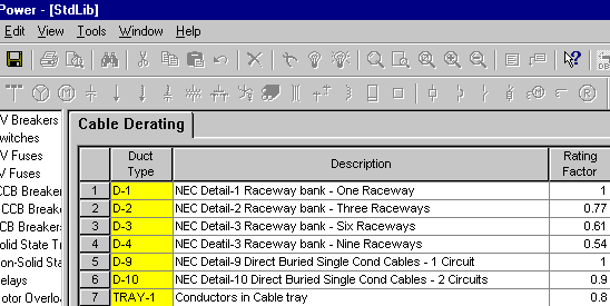
This field allows for cable ampacity derating based on the number of conductors in the conduit, tray or duct. Select from D-1, D-2, and so on, which correspond to NEC Detail 1, NEC Detail 2, and so on, of the National Electric Code. If this field is left blank, a 1.0 multiplier is assumed for the ampacity calculations. The rating factors are stored in the standard device library and can be customized if needed. If you need to derate cables based on number of conductors in the conduit or tray, you can add to the library.
Figure 5: Cable Derating in the Standard Device Library
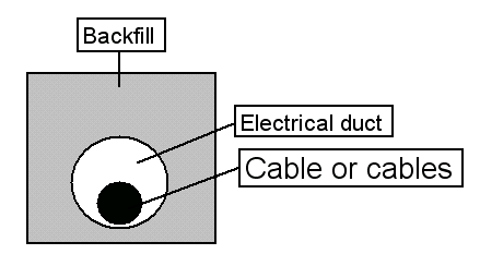
Figure 6: 11.5” X 11.5” Electrical duct bank. One electrical duct
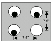
Figure 7: 19” X 19” Electrical duct bank. Three electrical ducts For a complete listing of duct configurations, please see article 310 in the National Electric Code. |
| Ambient Temp | Ambient air temperature. This is used for ampacity derating based on the standard selected in Tools > Options > Equipment. You can choose US (based on NEC), CSA (based on CEC) or <None> in the Options. No derating is applied when the option is <None>. |
|
Conductor Lay (AC cable only) |
Lay of the conductor, which affects the impedance. 3/C, IAA, IAS, and MAC configurations are always defined with a triangle configuration and zero spacing even if you choose a different configuration. Single conductor cables, however, can be in flat, triangle or a right triangle configuration with any spacing factor. |
| Conductor Form | Conductor form is determined by the extrusion process of the copper or aluminum. Select either round or sectored. |
| Conduit Size & Num | Size and number of conduits. This does not affect the impedance or ampacity calculations, but is stored as data. SmartDesign™ populates this field while automatically sizing the cables. |
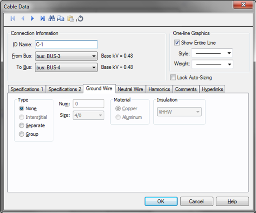
Figure 8: Ground Wire Tab of the Cable Data Dialog Box
| Option | Description |
|---|---|
|
Type (AC cable only) |
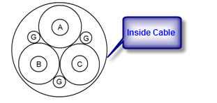
Ground conductor type (none, interstitial, separate, or as part of a group of conductors). This choice has an effect on the zero sequence impedance calculation. See Reference 1 for more information on ground impedance calculations. None: No ground conductor. Interstitial: The ground wires in a three conductor cable (or IAA, IAS, CLX, TEC). Typically there are three bare ground wires spaced evenly between the phase conductors.
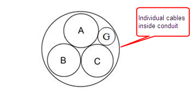
Figure 9: Interstitial Ground Separate: A separate ground conductor in a conduit for a specific circuit.
Figure 10: Separate Ground Group: A ground conductor in a duct bank or tray that is used for multiple circuits. |
| Num | Number of ground wires in the circuit. This value is for reference only and does not affect analysis. |
| Size |
Ground conductor size. This value is for reference only and does not affect analysis. Note: The size of ground wire may not have a direct influence on the effective zero sequence resistance (R0) and reactance (X0). Refer to Kaufmann’s paper on grounding. For steel conduits, ground currents flow through the conduit close to the outer surface because of skin effect. |
| Material | Ground conductor material. This value is for reference only and does not affect analysis. |
| Insulation | Type of insulation for the ground wire. Select <None> for bare conductor. This value is for reference only and does not affect analysis. |
All neutral wire fields are for reference only and do not affect analysis. Not applicable to DC cables.
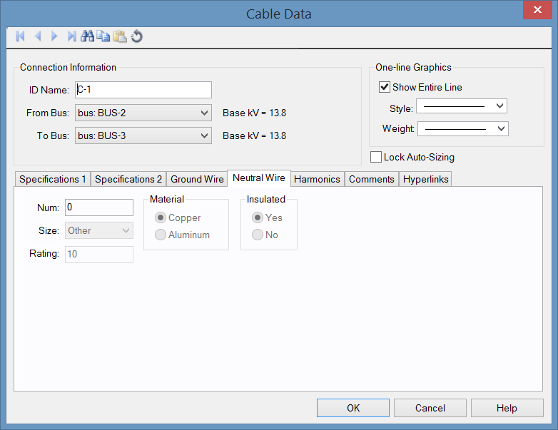
Figure 11: Neutral Wire Tab of the Cable Data Dialog Box (AC Only)
| Option | Description |
|---|---|
| Num | Number of neutral wires. |
| Size | Size of the neutral wire. |
| Rating | Amp rating of the neutral conductor. Enter amp rating based on size. |
| Material | Neutral material type (copper or aluminum). |
| Insulated | Whether or not the neutral conductor is insulated. |
Note: Not applicable to DC cables.
Use the Harmonics tab to indicate whether this equipment item is introducing harmonics into your power system.
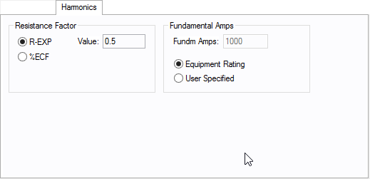
Figure 12: Harmonics Tab
| Option | Description | |||||||||||||||||||||
|---|---|---|---|---|---|---|---|---|---|---|---|---|---|---|---|---|---|---|---|---|---|---|
| Resistance Factor |
EasyPower offers two methods for calculating RH:
RH = RFund * H R-EXP RH = RFund * (1+ECF*H2)/(1+ECF) EasyPower defaults all skin effect correction to R-EXP and a value of 0.5.
|
|||||||||||||||||||||
| Fundamental Amps |
Use to set the fundamental amps. The options are as follows:
To use fundamental current calculated by power flow, select Calculated from Power Flow in the Summation Fundamental Voltage area of the Harmonics Options > Control dialog box. |
This tab is read-only and appears only if you have imported data from an SKM Data Format file. See Importing an SKM Format File for more information.
See Comments for information.
See Hyperlinks for information.
| Database Technical Reference |
|
|