You are here: Database Technical Reference > Filter Data

Filter Data

A filter is a passive tuned circuit that presents a low impedance “sink” to currents at a given frequency or frequencies. Filter on the equipment palette toolbar inserts a filter in the one-line diagram. The application of harmonic filters can cause the creation of parallel resonance below the filter tuning point (single tuned notch). The filter must be designed to minimize the impact of this resonant point.

This dialog box includes the following areas and tabs:

Figure 1: Filter Data Dialog Box

Connection Information

Option Description
ID Name Uniquely identifies the filter. This ID name can be up to 16 characters long. The names default to FL-1, FL-2, FL-3... as you enter new filters on the one-line, but these names can be changed to be more descriptive if needed.
To Bus The bus to which the filter connects, which must already exist on the one-line. For your reference, the To Bus base kV is displayed next to the bus name.

Specifications

Option Description
Type

You can select from four different types of filters. When you choose the type of filter, EasyPower makes unavailable any filter data fields that do not apply to the selected filter.

Figure 2: Filter Types

Filter Data
Resistor Resistance of resistor of the filter in ohms.
Inductor Real and imaginary impedances (ohmic resistance and inductive reactance) at system frequency in ohms.
Capacitor Bank (1 and 2) The reactive power of capacitors for the system frequency in MVARs at the voltage level specified in kilovolts.

Harmonics

Use the Harmonics tab to indicate whether this equipment item is introducing harmonics into your power system.

Figure 3: Harmonics Tab

Option Description
Resistance Factor

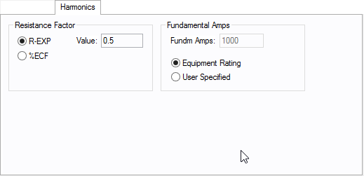
EasyPower offers two methods for calculating RH:

  • Resistance varying with a power of the harmonic (R-EXP):
  • RH = RFund * H R-EXP

  • Resistance varying with a percent eddy current factor (%ECF):
  • RH = RFund * (1+ECF*H2)/(1+ECF)

EasyPower defaults all skin effect correction to R-EXP and a value of 0.5.

Typical Resistance Correction Factors

  R-EXP %ECF

Transformer

0.5-1.0

1.0-3.0

Utility

0.0-0.8

    -

Generator

0.3-0.6

    -

Line/Cable

0.5

    -

Reactor

0.5-1.0

0.8-3.0

Motor

0.2-0.4

    -

Fundamental Amps

Use to set the fundamental amps. The options are as follows:

  • Equipment Rating sets Fundm Amps to the equipment rating of the item described in the Specifications tab. 
  • User Specified activates the Fundm Amps field, enabling you to specify a value. 

To use fundamental current calculated by power flow, select Calculated from Power Flow in the Summation Fundamental Voltage area of the Harmonics Options > Control dialog box.
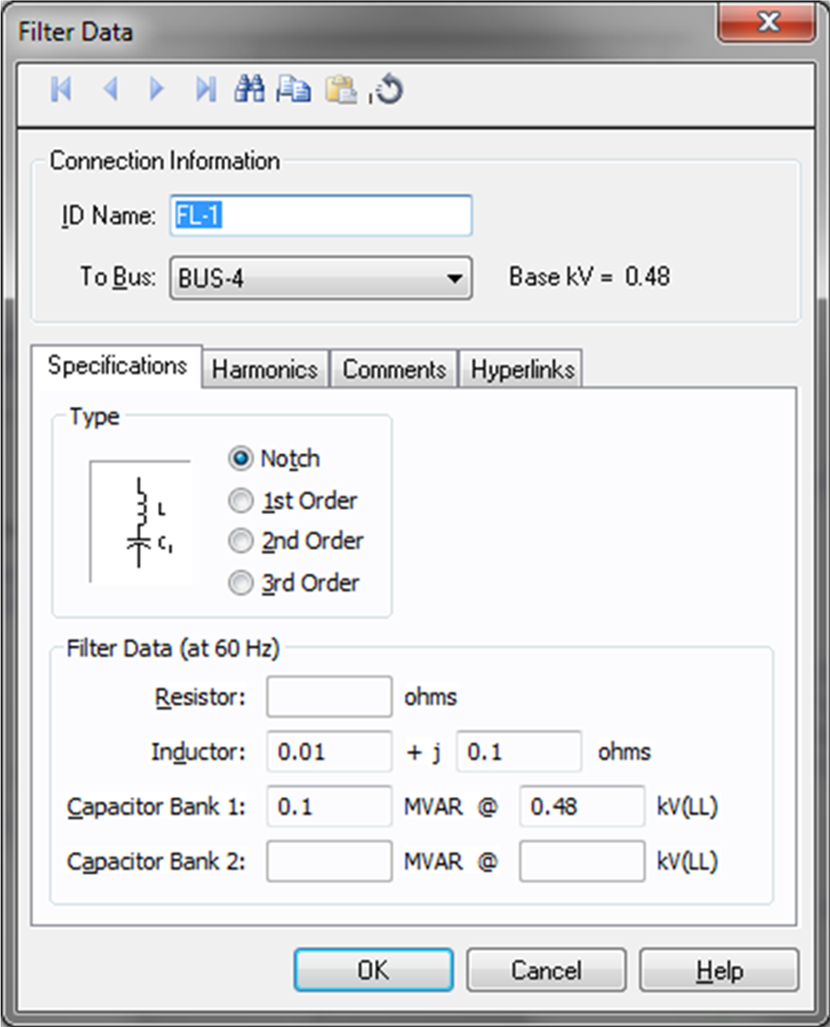
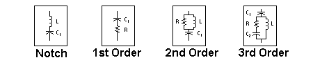
Location

See Location for more information.

Imported Data

This tab is read-only and appears only if you have imported data from an SKM Data Format file. See Importing an SKM Format File for more information.

Comments

See Comments for information.

Hyperlinks

See Hyperlinks for information.

More Information

Database Technical Reference  
     

www.easypower.com

EasyPower, LLC

7730 SW Mohawk St.

Tualatin, OR 97062

(503)655-5059

techsupport@easypower.com

feedback@easypower.com

EasyPower Version 9.7

Copyright © 1991-2016 EasyPower, LLC. All Rights Reserved.

Help was last updated on 2/8/2016