Here we demonstrate two simple shapes and show how they are put together to create a symbol. We use a utility, which is made up of rectangles and a line.
The text below shows the contents of the ANSI symbol file for an AC utility that is connected above a bus.
<SymbolTemplate>
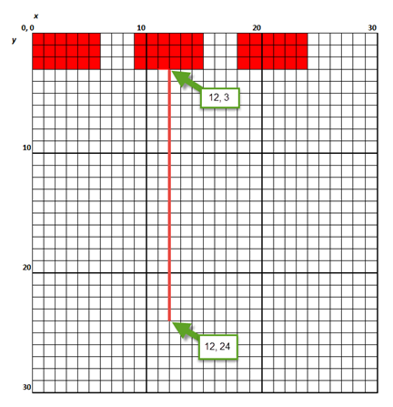
<Rectangle Left="0" Top="0" Width="6" Height="3" FillStyle="Solid"/>
<Rectangle Left="9" Top="0" Width="6" Height="3" FillStyle="Solid"/>
<Rectangle Left="18" Top="0" Width="6" Height="3" FillStyle="Solid"/>
<Line X1="12" Y1="24" X2="12" Y2="3" Width="1"/>
</SymbolTemplate>
The figure below shows the contents of the <SymbolTemplate> tag, as plotted on the grid. The red color is used for emphasis.
Note: For symbols including busway, cables, and transmission lines, the only styling options available are line width and style. These settings are used for the symbols when new items are added, but these can be overwritten by the settings in the data dialog boxes.
| Customizing One-line Symbols | Polylines |
| Symbol Definition Tags | Polygons |
| Coordinates | Text |
| Arcs and Circles | Bezier Curves |
|
|