Trip Devices
Relays
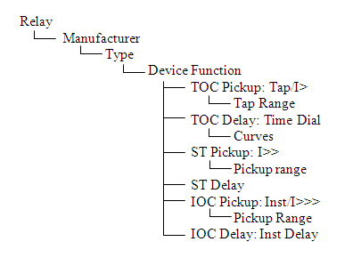
Figure 1: Tree Structure of Relay
Device Function: A tripping characteristics with only one time-overcurrent and one instantaneous overcurrent tripping functions. Device functions are listed as the ANSI code numbers or their combinations. You may enter your own device function names.
Single Function Relay: A single function relay has only one device function. If this is selected in the Relay Info tab while entering data, then you can select only one set of relay settings in the database edit mode.
Multi-function Relay: A multi-function relay has more than one device function. If this is selected in the Relay Info tab while entering data, then you can select multiple sets of relay settings in the database edit mode. If multi-function is selected and only one device function is entered in the library, then you can select different trip settings at the same time. Multiple curves can be plotted in coordination from the same relay. This feature is applicable to relays which can sense more than one current but operate with similar device functions.
Relay Class: You can choose from “Generator Relay,” “Motor Relay,” and “Other.” The choice of Relay Class affects the calculation method. For Generator Relay class and Motor Relay class, the trip settings are in multiples of full load amps (FLA). For the Other class the trip setting may be in multiples of relay rating, CT ratio, CT primary amps, and so on.
Molded Case Circuit Breakers (MCCB)
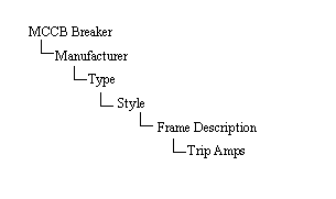
Figure 2: Tree Structure of MCCB Breaker
Style: A style is a group of MCCB breakers with the same brand, model, interrupting rating, similar trip characteristics, and similar frame size.
Frame Description: A Frame Description is a unique name that represents a unique set of trip characteristics data. If the same set of data applies to several Trip Amps ratings, then they can be entered as one frame description but with different Trip Amps. In most cases, the trip characteristics data for various MCCB ratings may be different although the same frame size is the same. In such cases, the data must be entered using different frame descriptions.
Frame Size: The Frame Size is the maximum rated continuous current that any frame can have. Typical frame sizes are 125A, 250A, 400A, 600A, 800A, etc.
Trip Amps: Trip Amps is the rated continuous current of the MCCB above which the device trips.
Solid State Trips
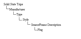
Figure 3: Tree Structure of Solid State Trips
Sensor Description: A Sensor Description is a unique name representing a set of trip characteristics data.
Plug: An SST with a given frame or sensor may have several different plugs to set the long time pickup current.
Non-Solid State Trips
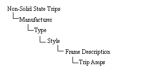
Figure 4: Tree Structure of Non-Solid State Trips
Style: A style is a group of non-solid state trips with the same brand, model, interrupting rating, similar trip characteristics, and similar frame size.
Frame Description: A Frame Description is a unique name that represents a unique set of trip characteristics data. If the same set of data applies to several Trip Amps ratings, then they can be entered as one frame description but with different Trip Amps.
Frame Size: The Frame Size is the maximum rated continuous current that any frame can have. Typical frame sizes are 125A, 250A, 400A, 600A, 800A, and so on.
Trip Amps: Trip Amps is the rated continuous current of the non-solid state trip unit above which the device trips.
High Voltage Fuses
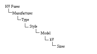
Figure 5: Tree Structure of HV Fuses
Model: Model usually represents the “speed” of the fuse, such as K, KS, T, and so on.
kV: The voltage level for which the fuse is applicable.
Sizes: The sizes of fuses available for a given model and kV rating. Although the size names correspond to their ampere ratings, the numbers within the size name are not necessarily the minimum melting amps.
Continuous Current: The rated continuous current of the fuse.
 Plot: Action button to plot the TCC curve for the data entered in the spreadsheet.
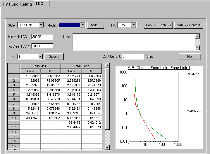
Figure 6: TCC tab of HV Fuses Dialog Box
Low Voltage Fuses
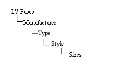
Figure 7: Tree Structure of LV Fuses
Low voltage fuses are similar to HV Fuses—see High Voltage Fuses. However, Model and kV are not part of the tree structure in LV Fuses.
Sizes: The sizes of fuses available for a given type. Although the size names correspond to their ampere ratings, the numbers within the size name are not necessarily the minimum melting amps.
Continuous Current: The rated continuous current of the fuse.
Plot: Action button to plot the TCC curve for the data entered in the spreadsheet.
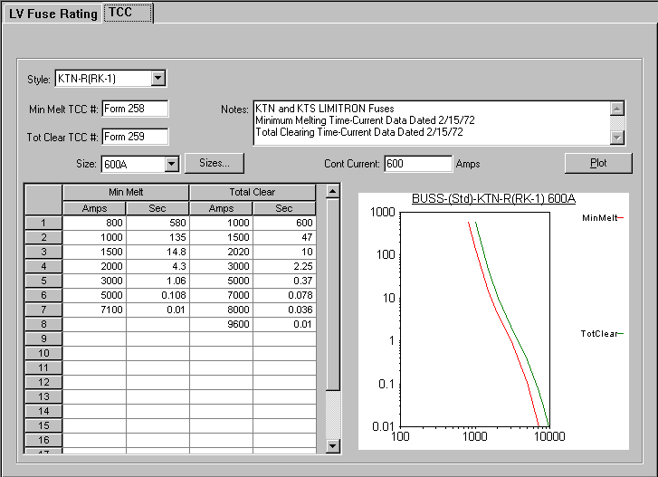
Figure 8: TCC tab of LV Fuse Dialog Box
Motor Overload Relays
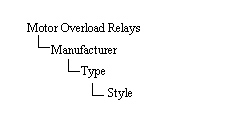
Figure 9: Tree Structure of Motor Overload Relays
Pickup Calculation: The trip amps is calculated as the trip data times the full load amps (FLA) of the motor. The FLA is not entered in the library. It is entered in the Motor Overload Relay dialog box in the one-line. The trip data entered in the library are per unit values for current.
Plot: Action button to plot the TCC curve for the data entered in the spreadsheet.
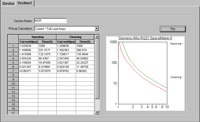
Figure 10: Section 1 Tab of Motor Overload Relay
More Information
| EasyPower Device Library |