Bus Data
This dialog box includes the following areas and tabs:
- Database Dialog Box Toolbar
- Connection Information
- Specifications Tab
- Switchgear/Panelboard/Switchboard Tab
- Equipment Elevation Tab
- Arc Flash Hazard Tab
- Accessories Tab
- Change Management Tab
See Common Tabs for information on the Location, Reliability, Comments, Hyperlinks, Media Gallery, or Collected Data tabs.
For DC buses, see also DC Bus - Base Voltage Specifications.
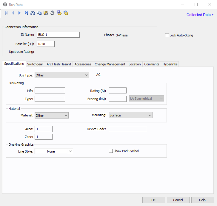
Figure 1: Bus Data Dialog Box
Connection Information
| Option | Description |
|---|---|
| ID Name |
Uniquely identifies the equipment item. The program automatically assigns a name, but you can change it, if needed. The name can be up to 16 characters long. For buses, the program automatically assigns the names BUS-1, BUS-2, BUS-3, and so on. |
| Base kV |
Base kV for the bus. Note that the bus must have a kV entered before equipment can be connected to the bus. Anything less than 1 kV is considered low voltage, anything 1 kV or more is high voltage. MCCs and panel schedules can only be connected to low voltage buses. For DC buses, see also DC Bus - Base Voltage Specifications. |
|
Phase |
The phase of the item. Currently, this is for reference only. |
| Lock Auto Sizing | When this check box is selected, this item cannot be automatically sized using SmartDesign™ (the auto-design feature). |
| Upstream Rating |
The minimum amp rating of equipment that is upstream from the bus (such as breakers, transformers, or cables). This information is for reference in certain specific configurations of EasyPower and is not generally visible. |
Specifications Tab
Switchgear/Panelboard/Switchboard Tab
This tab allows you to calculate downstream loads on all the branches breakers connected to the bus. This tab can be labeled as Switchgear, or Panelboard, or Switchboard depending on the Bus Type selected in the Specifications tab.
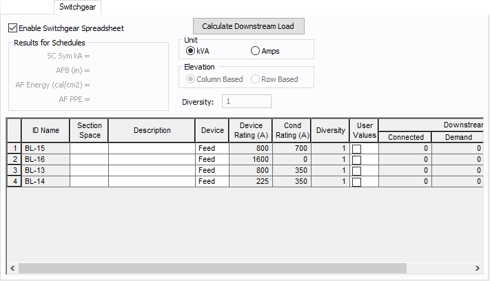
Figure 2: Switchgear Tab of Bus Data Dialog Box
| Option | Description |
|---|---|
| Enable Switchgear Spreadsheet | Selecting this check box enables you to modify information, enter load data and calculate downstream loads. Once you make the necessary data entry and calculations you can you can clear the check box to prevent changes. When the check box is not selected, the data can still be read, but not changed. |
| Calculate Downstream Load | Clicking this button calculates all downstream loads for each breaker, fuse, or branch connected to this bus. All branches are considered downstream unless there exists a source such as a UPS, generator or utility in the direction of the branch. The program traverses through all the paths and determines whether or not there is a power source in the path. All loads are summed and reported in the spreadsheet if there is no power source in the path. |
|
Results for Schedules |
For the bus types ATS, switchgear, switchboard, panelboard, panel and MCC, you can fault buses and store the short circuit current and arc flash results in the database. These results can be displayed in schedules for switchgear, switchboard, panelboard, panels and MCCs. The stored results can also be viewed in the database browser and report. See Storing Short Circuit and Arc Flash Results for more information. |
| Unit | You can display downstream loads in kVA or Amps. |
| Elevation | You can choose the elevation layout of the switchgear such that protective devices in stacked in columns or rows. For columns, the breakers in one unit are stacked vertically. For rows, you can have a single breaker, or breakers on the left or right. See Elevation View for more information. |
| Diversity | Enter the diversity factor for the bus. The factor is used in calculating connected, demand, code, and design kVA. The diversity factor is the ratio of the sum of the maximum demands of the individual loads to the maximum demand of the entire system, including all of those loads. Enter a value between 1 and 10. |
| Spreadsheet Column Headings | |
| ID Name | ID name of the equipment connected to the bus. If any branch has a protective device such as a switch, fuse or breaker connected to the bus, then the ID name of the protective device is shown. Otherwise the branch ID name is shown. |
| Section Space | Text that describes the space for the protective device or branch. |
| Description | Text that describes the branch connected to this bus. |
| Device | You can specify the protective device or branch as Feeder, Main, or Tie. This is for information only and does not affect calculations. |
| Diversity |
The number shown is the diversity factor of the downstream bus with an equipment type of Switchgear, Switchboard, or Panelboard. If another equipment type is selected, the diversity factor is set to 1. Diversity factor is used in calculating the connected, demand, code and design kVA. The diversity factor is the ratio of the sum of the maximum demands of the individual loads to the maximum demand of the entire system, include all of those loads. Click Calculate Downstream Load to update the diversity factor. |
| Device Rating (A) | Continuous current rating of the protective devices in amps. |
| Cond Rating (A) | Amp rating of branch conductors. |
| User Values | Select the check box to manually enter a load. When checked, the entered values are used and the calculated downstream values from the one-line are ignored. |
Equipment Elevation Tab
For information on this tab, see Elevation View.
Arc Flash Hazard Tab
The Arc Flash Hazard tab enables you to specify the necessary details of the equipment for arc-flash hazard calculations.
EasyPower calculates arc flash risk assessment results using the options set on the Arc Flash Hazard tab. The results are calculated for automatic transfer switches, buses, tool points of connection, MCCs, and panels.
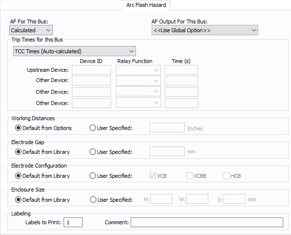
Figure 3: Arc Flash Hazard Tab
| Option | Description |
|---|---|
| AF For This Bus |
You can specify how you would like arc flash results determined for this bus using AF for this Bus. Calculated: When the bus is faulted, EasyPower the performs arc flash hazard analysis using the calculation method specified in Short Circuit Options. EasyPower uses other settings on this tab as part of the calculations. Excluded: Select to exclude the bus from arc flash reports. An example of when you might select this option is for a bus that is required to model the electrical parameters of the system but does not actually represent a piece of electrical equipment. Other applications include nodes and tap-offs (junctions), where energized work is not required. Forced To: When you select this option, you can enter the incident energy and arc flash boundary for this bus. The incident energy and arc flash boundary values are shown on the one-line and in reports and work permits. This can be used for instances where you need to apply a calculation that is outside the scope of the industry standard calculations. |
| AF Output For This Bus |
You can specify whether to display results on the line side or the load side of the Main protective device of the bus equipment. If the arc flash hazards output for this bus needs to be different from the global option, use this field. The choices are:
|
| Trip Times for this Bus |
You can select the method for determining trip times for this bus by choosing from the following:
Note: When a user-defined time is specified and the calculation method is set to use the integrated method, only the upstream device setting is used. The time is considered as the maximum length of the simulation. See The Integrated Method for more information. |
| Working Distances |
You can specify the working distances shown on the one-line and in reports and work permits.
The units displayed are based on the units selected in Arc Flash Hazard Options on the System tab. For inches, the range is 1-1000. For meters, the range is 0.1 to 1000. |
| Electrode Gap |
You can specify the electrode gap shown on the one-line and in reports and work permits.
|
|
Electrode Configuration |
You can specify the electrode configuration shown on the one-line and in reports and work permits.
Electrodes in Enclosures: Electrodes in Open Air: You can select more than one configuration to represent the multiple types of conditions that can occur for the equipment. EasyPower evaluates each configuration and then provides values for the highest incident energy based on the existing electrode configurations. Annex C in the IEEE 1584-2018 standard describes examples where you might use more than one electrode configuration. Tip: To change the electrode configuration for multiple items on the one-line, select the items in the Database Edit focus and then on the Home tab, click Change > AF Bus Electrode Configuration. Electrode configurations are only applicable to the IEEE 1584-2018 standard. For more information, see Electrode Configuration. |
|
Enclosure Size |
You can specify the enclosure size shown on the one-line and in reports and work permits.
The units displayed are based on the units selected in Arc Flash Hazard Options on the System tab. For inches, the range is .01-1000. For millimeters, the range is 0.1 to 25,000. The enclosure dimensions affect arc flash.
|
| Labels to Print |
Enter the number of labels you want to print for arc flash hazard analysis. If you enter "0," no labels will print. |
| Comment |
You can type a comment that appears on the arc flash label when it is printed. For example, you could type a location description for the equipment to assist with label placement. |
Accessories Tab
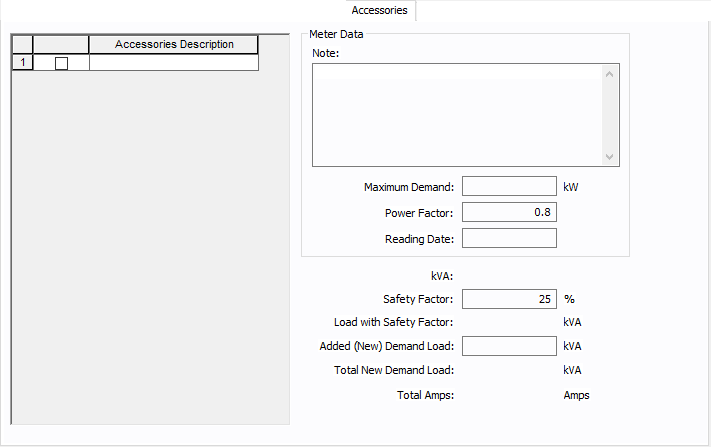
Figure 4: Accessories Tab
| Option | Description |
|---|---|
| Accessories Description | The accessories for distribution equipment types can be specified in the panel, MCC, and bus dialog boxes. You can add or delete the accessory items as needed per equipment. Only the selected items are displayed in the schedule outputs. |
| Meter Data | |
| Note | An accessory note of up to 1,024 characters. |
| Maximum Demand | The maximum demand load at this equipment. |
| Power Factor | The power factor for the equipment. |
| Reading Date | The date the meter was read or the information was gathered. |
| kVA | |
| Safety Factor | Percentage above the kVA that will be multiplied to calculate the new safety factor load. |
| Load with Safety Factor | Load amount after calculating the safety factor. |
| Added (New) Demand Load | User-specified load amount to add to the equipment. |
| Total New Demand Load | Total of the load with safety factor and the added demand load. |
| Total Amps | Amps based on the total demand load. |
Change Management Tab
Note: This information is used in certain specific configurations of EasyPower and is not generally visible.
See Buses and Panels in Change Management Help for details.
Other Tabs
See Common Tabs for information on the Location, Reliability, Comments, Hyperlinks, Media Gallery, or Collected Data tabs.
More Information
| Database Technical Reference | Common Tabs |
| DC Bus - Base Voltage Specifications | Electrode Configuration |
| Media Gallery |