Elevation View
You can create the elevation view for MCC and buses (switchgear, switchboard and panelboard) and print the view. You define the size and location of buckets, breakers or cubicles using the fields Column Number and Space.
To create the elevation view, you must first define the Column Number and Starter/Row Space in the dialog box for the bus or the MCC. The Equipment Elevation tab displays the elevation view.
MCC Elevation
In the Description tab of the MCC dialog you can specify the location and size of each bucket (space). The Equipment Elevation tab of the MCC dialog displays the elevation drawing. You can print the elevation view by clicking  Print while the Equipment Elevation tab is selected.
Column Number: This is the ordinal number of the column in which the starter (bucket) is located. The columns are arranged in increasing order starting from 1 and ending in the highest column number. See the picture below of Equipment Elevation and the corresponding Description tab.
Starter Space: Height of the space in terms of the column width.
If there are multiple items in the same column, they appear in the order they are entered in the Description spreadsheet.
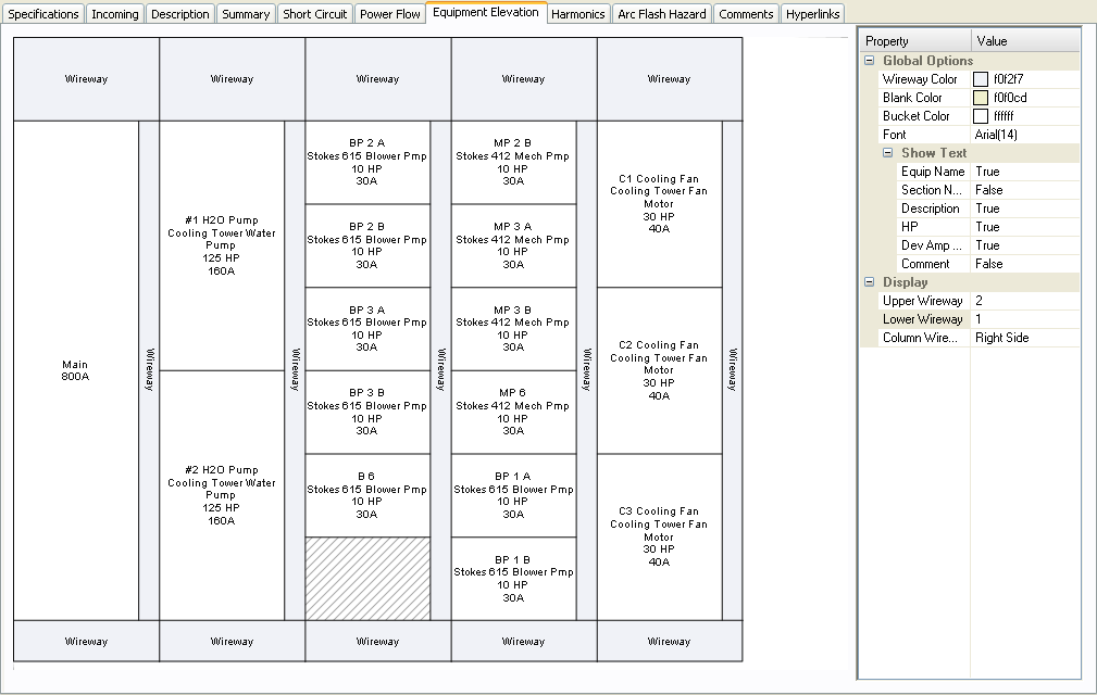
Figure 1: MCC Elevation View
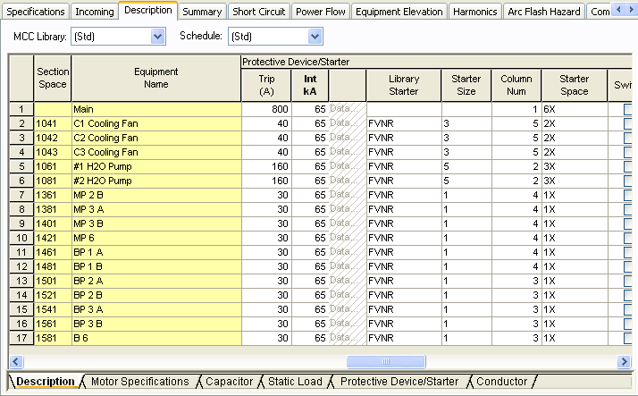
Figure 2: Specifying Column Number and Starter Space in the Description tab
You can show text from the fields: Equipment Name, Section Name, Description, HP, Protective Device Amps and Comments.
To show the main breakers in the elevation view, enter a new row in the Description tab, enter the Load Type as Load, and enter the description.
In the Property pane on the right of the elevation, you can:
- Specify the height for the top and bottom horizontal wireways and the vertical wireway.
- Change the column number and space size by selecting the bucket first in the elevation and then changing the parameters.
To print the elevation view, click Print on the MCC toolbar.
Switchgear Elevation
If you have defined the bus type as switchgear, you can view the elevation for the switchgear. In the Bus Data dialog box, on the Switchgear tab, you can specify whether the elevation layout is based on columns or rows. For columns, the breakers in one unit will be vertically stacked. For rows, you can have single breakers throughout the row (2X), or breakers on the left (1X-Left) or right (1X-Right).
For column-based elevation, specify the Column Number and Row Space for each row of data. This creates the elevation view.
Column Based
Column Number: This is the number of the column in which the cubicle (for breakers) is located. The columns are arranged in increasing order starting from 1 and ending in the highest column number. See the pictures below of Equipment Elevation and the corresponding Switchgear tab.
Row Space: Height of the space in terms of the column width.
Row based
Column Space: You can specify the size and side of the breaker spare in the panelboard. The breakers appear in order, with the first row showing at the top.
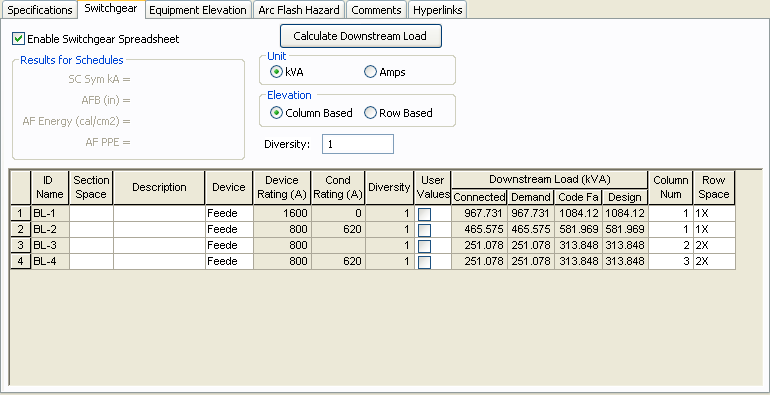
Figure 3: Column Number and Row Space on the Switchgear tab of the Bus Data Dialog Box
You can show the text for Equipment Name, Section Space, Description and Device Rating by setting the values in the Property pane.
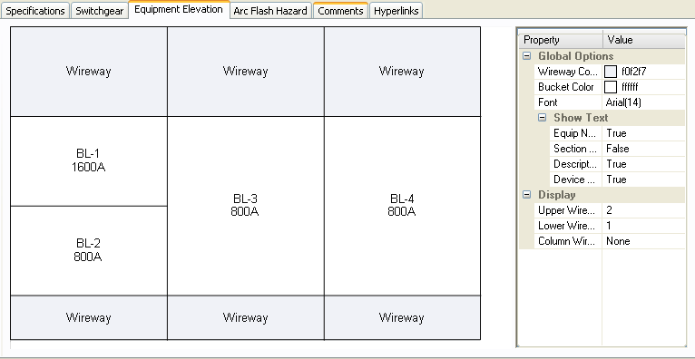
Figure 4: Switchgear Elevation
In the Property pane on the right of the elevation, you can:
- Specify the height for the top and bottom horizontal wireways and the vertical wireway.
- Change the column number and space size by selecting the cubicle first in the elevation and then changing the parameters.
Inserting rows in the Switchgear spreadsheet: You can right-click on the spreadsheet and click Insert Row or Append Row.
To print the elevation view, click Print on the Bus Data dialog box toolbar.
Switchboard Elevation
Switchboard elevation (where you have defined the bus type as Switchboard) is viewed in the same way as switchgear.
Panelboard Elevation
If you have defined the bus type as Panelboard, you can view the elevation for the panelboard. The dialog and elevation are similar to that of switchgear. You can specify whether the elevation layout will be based on columns or rows. For columns, the breakers in one unit will be vertically stacked. For rows, you can have single breakers throughout the row, or breakers on the left or right.
Column Space: You can specify the size and side of the breaker spare in the panelboard. The breakers appear in order, with the first row showing at the top.
See the following picture of the Equipment Elevation and the corresponding Panelboard tab.
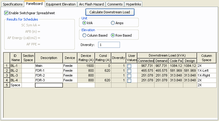
Figure 5: Defining Column Space in a Panelboard Tab
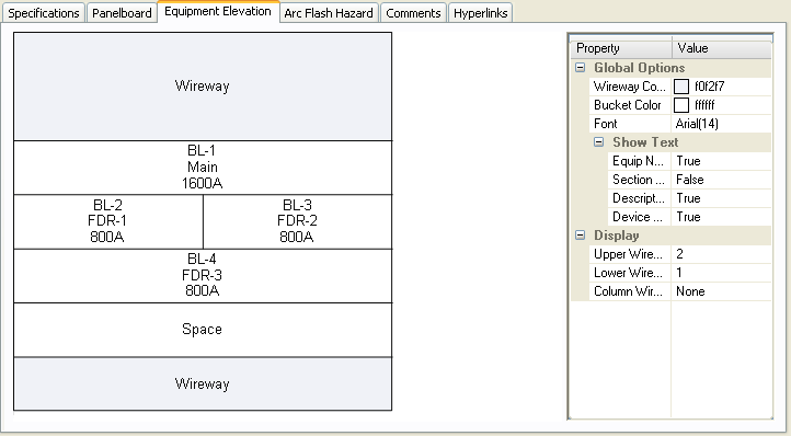
Figure 6: Panelboard Elevation View
In the Property pane on the right of the elevation, you can:
- Set values to show the text for Equipment Name, Section Space, Description and Device Rating.
- Specify the height for the top and bottom horizontal wireways and the vertical wireway.
- Change the space size by selecting the cubicle first in the elevation and then changing the parameters.
To print the elevation view, click Print on the Bus Data dialog toolbar.
Printing Elevations
You can also print elevation views by clicking File > Print > Print Elevations. In the Print Elevations dialog box, select the items you want to print.
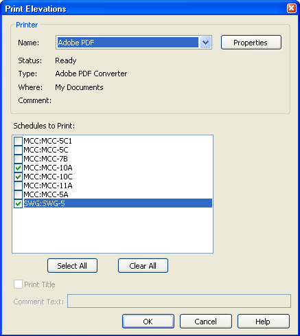
Figure 7: Print Elevations Dialog Box
More Information
| Making One-line Diagrams | |
| Motor Control Center (MCC) Data | |
| Switchgear/Panelboard/Switchboard Tab |