Coordination Focus
After you complete entering data of protective devices in the one-line diagram, you can plot their TCC curves. To do so, click  Coordination.
- When you enter the coordination focus, the Coordination tab is displayed.
- When you plot a TCC the TCC tab is displayed.
Coordination Tab (ANSI)
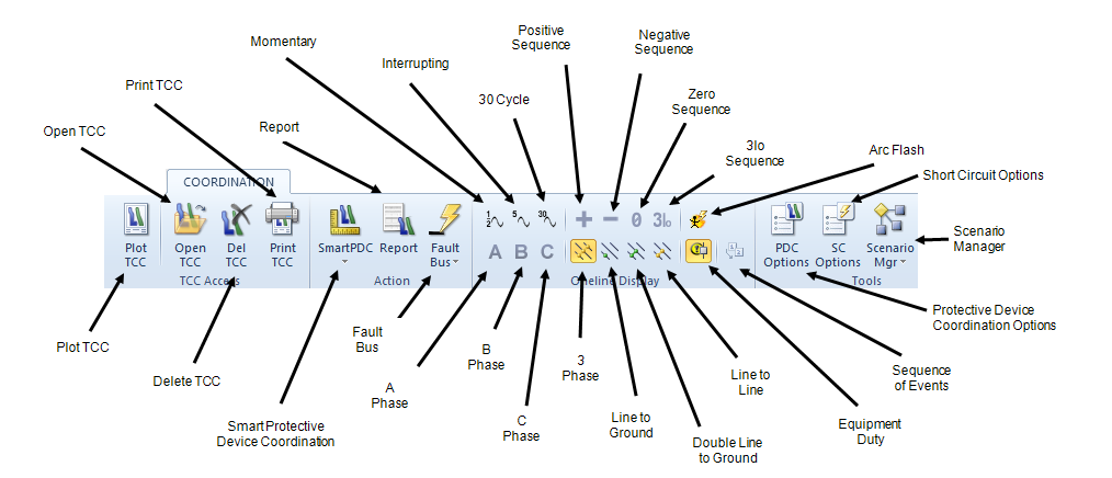
Figure 1: Coordination Tab
Coordination Tab (IEC)
The Coordination tab for IEC is similar to ANSI, but includes the following differences.
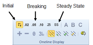
Note: SmartPDC is not currently available in Coordination for IEC.
Figure 2: Coordination tab for IEC
TCC Tab
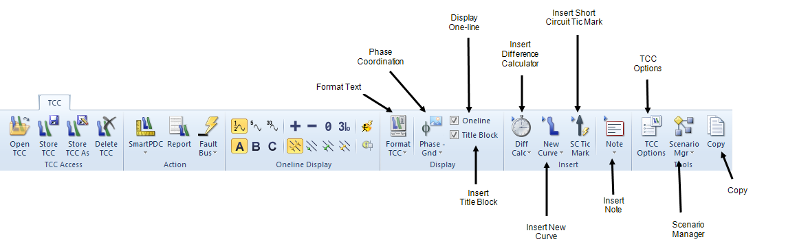
Figure 3: TCC Tab
Note: The TCC Access, Action, and Oneline Display buttons for the TCC tab are the same as those for the Coordination tab for ANSI and IEC. SmartPDC and Arc Flash are not currently available for IEC.
TCC Status Bar

Figure 4: TCC Status Bar
The TCC status bar appears at the bottom of the window and indicates the following settings:
|
Option |
Description |
|---|---|
|
Displays SNAP if grid snapping is on. See The Snap Grid for more information. |
|
|
Fault Type |
Displays the selected fault type. |
|
Calc Method |
Calculation method (ANSI or IEC) selected in Tools > Options > System. |
|
Voltage |
Either kV or per-unit. |
|
Driving Point kV |
The driving point voltage value as set in Short Circuit Options on the Control tab. |
|
Displays the coordinates of the pointer arrow on the time-current curve by current (amperes) @ time (seconds). |
More Information
| Coordination with PowerProtector™ | Plotting a TCC Curve from a One-Line |
| Plotting Motor Starting Curve on TCC | Plotting Items in MCCs and Panels |