Tick Marks
Insert SC Tick Marks
To insert user-defined short circuit tick marks on the TCC plot, on the TCC tab, click  Insert SC Tick Mark.
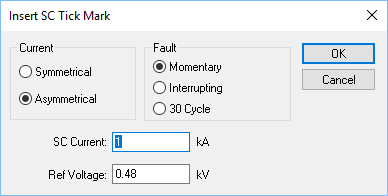
Figure 1: Insert SC Tick Mark Dialog Box (ANSI)
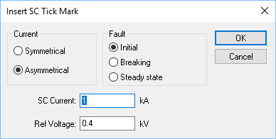
Figure 2: Insert SC Tick Mark Dialog Box (IEC)
|
Option |
Description |
|---|---|
|
Current |
You can select the appearance of the symbol that represents the short circuit current type.
These are default settings and can be edited by formatting tick marks. You can also save the format as new default tick marks.
|
|
Fault |
Selection of fault type affects the time coordinates of the tick mark.
The short circuit tick mark may be dragged vertically within a limited distance. |
|
Short Circuit Current |
Enter the short circuit current value in kilo amps The tick mark is placed on the TCC plot at the specified current value times the ratio of short circuit reference voltage to TCC plot reference voltage. |
| Reference Voltage | Enter the reference voltage at the short circuit point in kilo volts. The tick mark is placed on the TCC plot at the specified current value times the ratio of short circuit reference voltage to the TCC Scale reference voltage. |
Formatting SC Tick Marks
To format a short circuit tick mark to the desired shape, color and size, click the arrow below  Format TCC and select SC Tick Mark from the list.
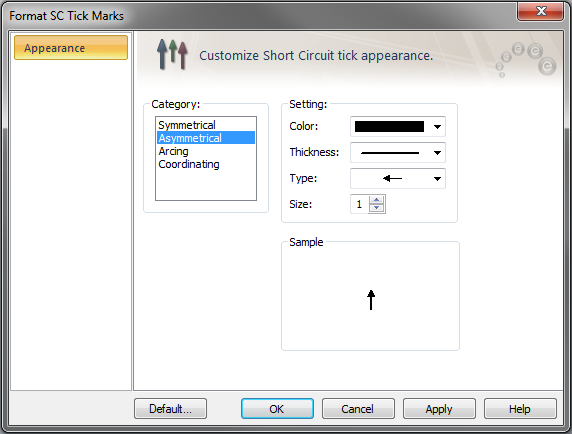
Figure 3: Format SC Tick Mark
This sets the format for all tick marks in the TCC that are of the same category. You can also set this as the default format for tick marks for all new TCCs by clicking the Default button.
Arcing Current Tick Mark
Arcing current tick mark represents the current through a protective device for an arcing fault (arc flash). You can insert an arcing current tick mark after faulting a bus on the one-line by right-clicking on the TCC curve and clicking Insert Arcing Current Tick Mark.
Note: This option is available only if your program has the Arc Flash feature. It is not available for IEC.
LV Breaker Series Coordination Tick Mark
As per manufacturer’s publications, low voltage breakers in series can be selectively coordinated in the instantaneous trip region up to a certain short circuit level although the TCC plot may indicate otherwise. If two breakers plotted on the TCC have series coordination data specified in the library, then a tick mark appears to indicate the maximum short circuit current up to which coordination is possible. If a breaker style is changed in a TCC plot, the TCC needs to be plotted again to get the new series coordination tick mark.
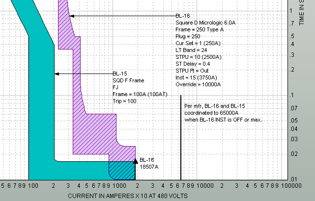
Figure 4: Series Coordination Tick Mark
More Information
| Coordination with PowerProtector™ |