Troubleshooting Arc Flash Hazard Results
Some of the frequently asked questions are listed below.
Arc flash hazard is not calculated and the report shows “No Valid Trip Device Found Upstream or in Bus Dialog.”
All buses that are analyzed require either an upstream trip device with all the necessary information entered, or arcing duration specified in the Bus Data dialog box. The program can determine arcing duration based on the time-current characteristics (TCC) of the trip device. The TCC can be determined only if all the necessary information has been entered in the trip device dialog box. For more information on protective data, see Coordination with PowerProtector™.
Checklist for trip device data:
HV Fuses: Manufacturer > Type > Style > Model > Fuse Size.
LV Fuses: Manufacturer > Type > Style > Fuse Size.
Thermal Magnetic LV Breakers: Manufacturer > Type > Style > Frame > Trip Amps > Instantaneous Setting (if applicable).
Solid State Trip LV Breakers: Manufacturer > Type > Style for breaker. AND for solid state trip Manufacturer > Type > Style > Frame/Sensor > Tap/Plug > LTPU > LT Delay > STPU > ST Delay > Inst Pickup for Phase Trip.
Relays: Manufacturer > Type > Device Function > Tap > Time Dial > Inst Pickup > Inst. Delay (whatever is applicable) for phase.
Note: Ground trips are ignored for arc flash when the 3-phase fault type is selected.
The Arc Flash Hazard report shows upstream devices that do not exist on the one-line.
There are two ways this can happen:
- Bus Data has user-defined trip times.
- Bus Data has pre-defined fixed times. The trip times specified in the library are used. Based on the voltage of the faulted bus, you could see the following in the column Upstream Trip Device Function:
|
LV Bus |
MV Bus |
|---|---|
|
INST |
50 |
|
ST-MIN |
51-MIN |
|
ST-INT |
51-INT |
|
ST-MAX |
51-MAX |
Downstream buses are showing greater hazard than upstream buses.
This is very typical when upstream trip device has inverse time characteristics. The lower fault currents at downstream buses cause longer trip times. Longer arc duration causes higher hazard level.
Arc Flash Hazard report indicates a trip device that is upstream to the trip device I expect will trip first.
Check to see if the protective devices are well coordinated. You can plot the TCC for both devices. Any overlap indicates miscoordination, which is not uncommon.
EasyPower selects the fastest tripping device for series path. For parallel paths, the slowest tripping device is selected for conservative results.
Arc Flash Hazard results of almost identical buses are significantly different although the fault currents and trip times are similar.
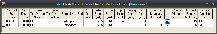
Figure 1: Similar Buses with Different Results
If your arc flash standard is set to something other than IEEE 1584-2018, this can be due to differences in grounding. The Arc Flash Hazard Report above shows that BUS-4 is solidly grounded. Notice the “X” in the column Gnd. As per IEEE 1584-2002 equations, resistance grounded/ungrounded systems have higher incident energy than similar but solidly grounded systems. For details, see Determination of System Grounding.
Note: The IEEE 1584-2018 standard no longer includes grounding in its calculations.
The report displays an "Out of IEEE 1584-2018 Range" message.
The program displays this message when any of the equipment parameters are outside of the range established by the IEEE 1584-2018 standard. For information on the parameters, see IEEE 1584-2018 Range of Model.
More Information
| Arc Flash Hazard Analysis |